Firearm with reciprocating bolt assembly

a reciprocating bolt and firearm technology, applied in the field of semi-automatic mechanisms, can solve the problems of insufficient delay, inconvenient use, and inability to provide high-power rimfire cartridges, so as to achieve the effect of reducing the number of cartridges out of battery firing, enhancing reliability and minimizing the out-of-battery firing of cartridges

Active Publication Date: 2016-12-06
SAVAGE ARMS
View PDF54 Cites 16 Cited by
  • Summary
  • Abstract
  • Description
  • Claims
  • Application Information

AI Technical Summary

Benefits of technology

[0003]In particular embodiments, a system delays blowback in firearms with reciprocating bolt assemblies in semiautomatic firearms and is particularly suitable for high power necked rimfire cartridges. A feature and advantage of embodiments of the invention is that enhanced reliability and minimization of out-of-battery firing of cartridges is provided. In embodiments, a semiautomatic firearm utilizes cooperating and common components to provide both a delayed blowback and a lockout of the firing pin when a bolt assembly is out-of-battery.
[0004]In embodiments of the invention, a movable member within a bolt body functions as a blocking member that blocks the firing pin and preventing the firing pin from striking a cartridge when the bolt is not in battery. In embodiments, the firing pin has two stop portions that the movable member can engage depending on the cycle status of the firearm. One stop portion, when blocked, prevents the firing pin from traveling into cartridge headspace when the hammer receiving end of the firing pin is struck by the hammer, the other stop portion, when blocked, prevents the firing pin from retracting to the ready to fire position such that the hammer receiving end of the firing pin is not exposed and thus cannot be struck.

Problems solved by technology

Such mechanisms require that the cartridge be retained in the firing chamber essentially until the bullet has left the barrel or the projectile velocity and performance will be impaired.
These mechanisms have not been proven suitable for high power necked rimfire cartridges due to the higher power and much greater rearward blowback force associated with these cartridges.
Such mechanisms, for these cartridges, do not provide enough delay in the blowback of the bolt or the bolt weight is excessively heavy.
The cycling mechanisms for the more powerful necked centerfire cartridges are not suitable either in that the rimfire cartridges generally do not provide sufficient gas pressures for such mechanisms, for example, gas operated cycling mechanisms used in AR-15 type rifles.
Even if such mechanisms could be adapted to the necked rimfire cartridges, such mechanism are complicated, requiring many moving parts and thus would be relatively expensive; particularly compared to semiautomatic .22 caliber non-necked rifles.
Previous attempts at reasonably priced consumer oriented semiautomatic rifles for these high power rimfire cartridges have had performance issues, such as jamming and out-of-battery firing of cartridges.

Method used


Image

  • Firearm with reciprocating bolt assembly
  • Firearm with reciprocating bolt assembly
  • Firearm with reciprocating bolt assembly

Examples


Embodiment Construction

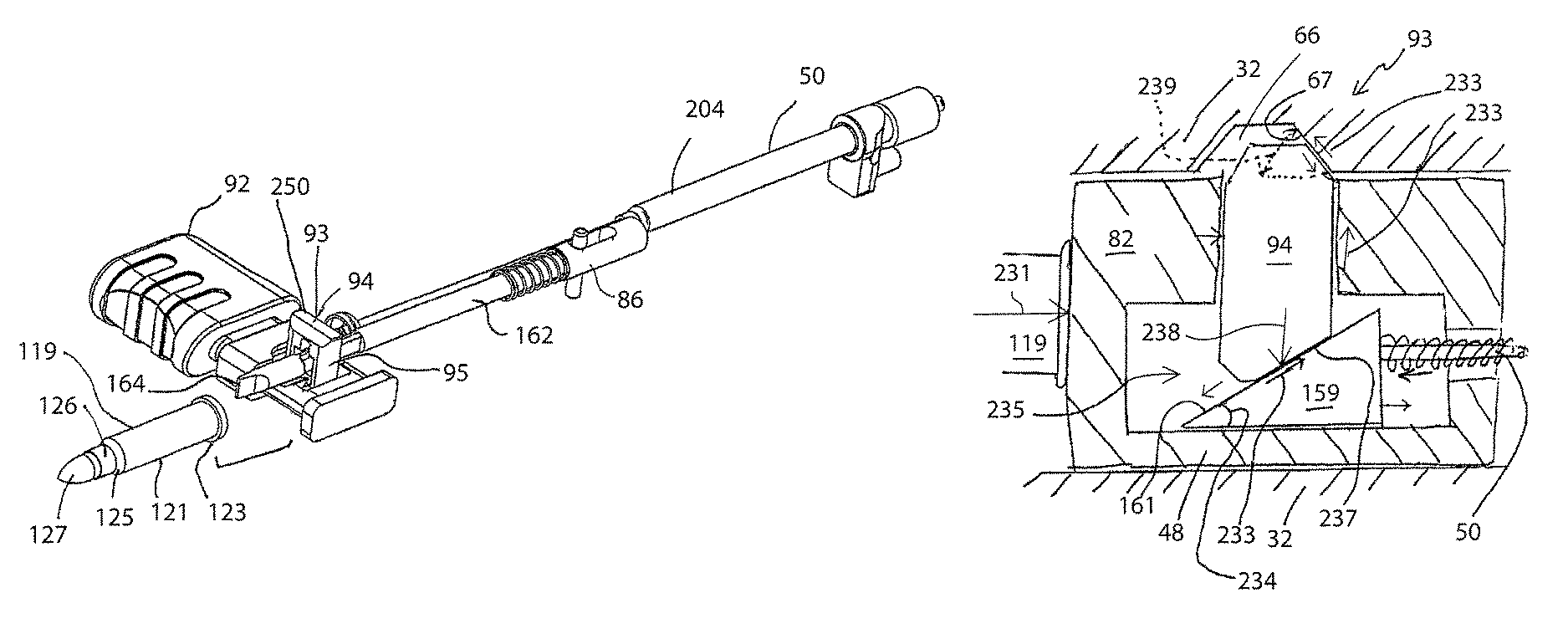
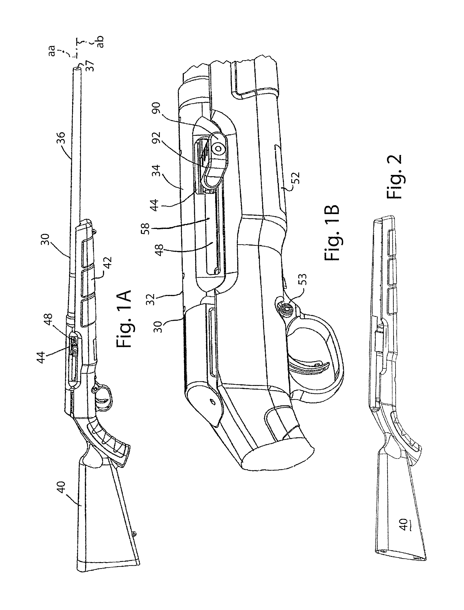
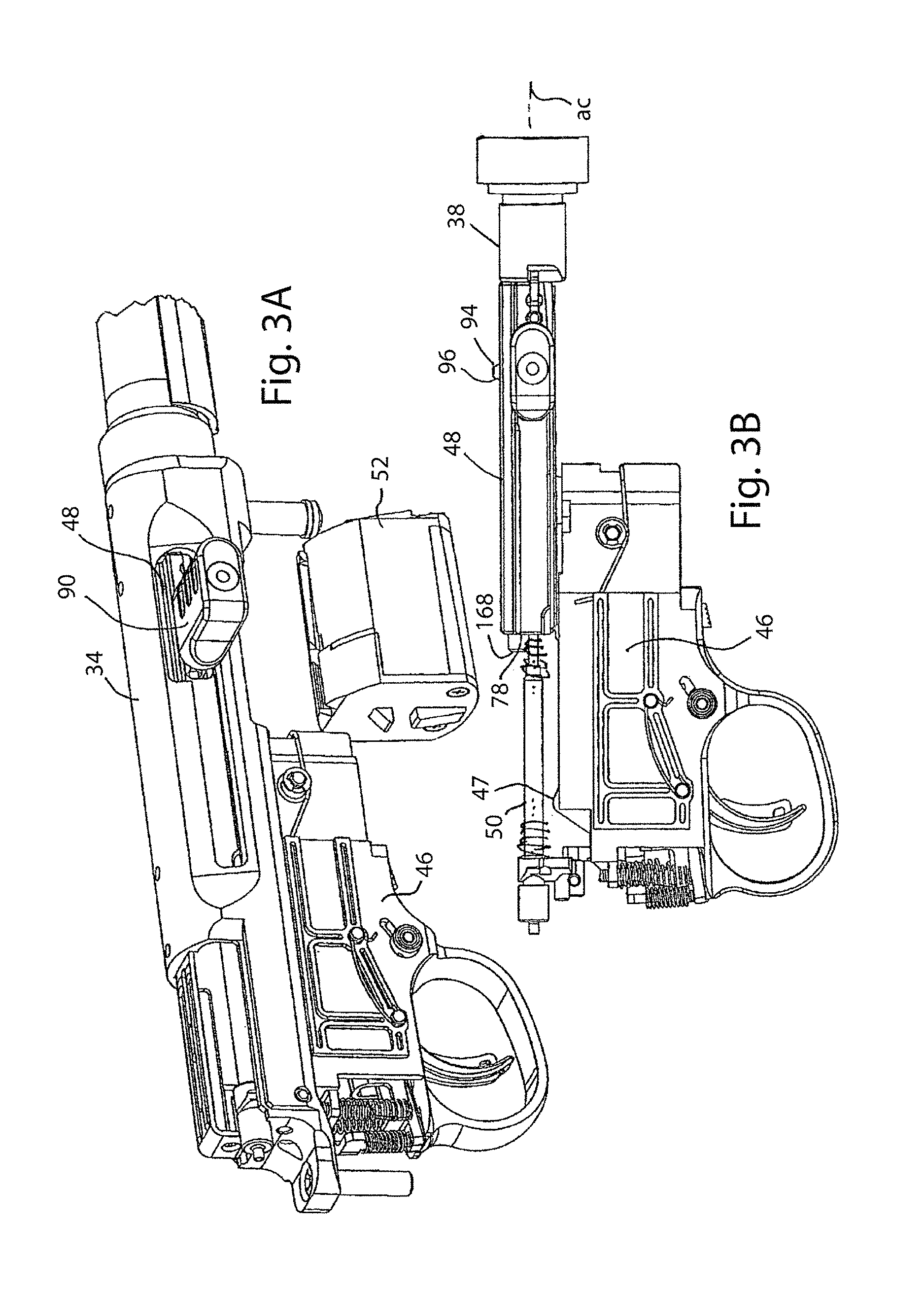
[0079]Referring to FIGS. 1A-4, a semiautomatic firearm 30 according to embodiments of the invention is illustrated and generally comprises a housing 32 including a receiver 34, a barrel 36 with a bore 37 and a firing chamber 38, a stock 40 with a forestock portion 42, an ejection port 44, a trigger and firing assembly 46 with a hammer 47, a bolt assembly 48, a recoil spring assembly 50, and a magazine 52. In one example, the trigger and firing assembly may be inserted into the unitary stock and forestock component as shown in FIG. 2. Then the barrel and upper receiver assembled on top of that and coupled to the trigger and firing assembly. The bolt assembly and recoil spring assembly inserted into the rear upward opening 56 of the receiver with panels added.

[0080]The bolt assembly 48 is slidingly engaged in the receiver 34 to move forwardly and backwardly along a bolt assembly travel axis aa which also is also coincident with a barrel axis ab of the bore 37 and is generally a centra...


PUM


Abstract

A semiautomatic firearm with a reciprocating bolt assembly has delayed blowback and a firing pin block. The firearm is particularly suitable for firing necked rimfire cartridges with a high level of reliability. Features prevent out-of-battery firing, when the bolt assembly is not fully engaged to the firing chamber or barrel face, a movable member within a bolt body functions as a blocking member that blocks the firing pin and prevents the firing pin from striking a cartridge. In embodiments, the firing pin has two stop portions that the movable member can engage depending on the cycle status of the firearm. A reverse cam mechanism associated with the firing pin blocking provides a resistance to and delays blowback. The bolt may interface with the necked rimfire cartridge using a undercut engagement on the forward end of the bolt. The semiautomatic firearm also may incorporate one or both of a dual trigger arrangement as part of a trigger and firing mechanism.

Description

RELATED APPLICATIONS[0001]This application claims the benefit of U.S. Provisional Patent Application No. 61 / 993,541, filed May 15, 2014; U.S. Provisional Patent Application No. 61 / 993,563, filed May 15, 2014; and U.S. Provisional Patent Application No. 61 / 993,569, filed May 15, 2014, each of which are incorporated by reference herein. This application is related to co-pending U.S. application Ser. No. 14 / 599,396, entitled SEMIAUTOMATIC FIREARM, filed Jan. 16, 2015 and co-pending U.S. application Ser. No. 14 / 599,199, entitled EXTRACTOR MECHANISM FOR FIREARM, filed Jan. 16, 2015. The above-recited applications are hereby incorporated by reference herein in their entirety.BACKGROUND OF THE INVENTION[0002]The invention relates to cycling mechanisms for firearms, specifically for semiautomatic mechanisms. Such mechanisms require that the cartridge be retained in the firing chamber essentially until the bullet has left the barrel or the projectile velocity and performance will be impaired...

Claims


Application Information

Patent Timeline
Patent Type & Authority Patents(United States)
IPC IPC(8): F41A15/14F41A19/16F41A3/12F41A3/66F41A19/27F41A21/00F41A3/46F41A19/10F41A19/12F41A19/14F41A17/46
CPCF41A15/14F41A3/12F41A3/46F41A3/66F41A19/10F41A19/12F41A19/16F41A19/27F41A21/00F41A17/46F41A19/14F41A3/72F41A3/70
Inventor KOLEV, IVANLINSCOTT, JOHN
Owner SAVAGE ARMS
Why Eureka
Try Eureka