Detachable machine control panel with display

a machine control and display technology, applied in the field of displayable machine control panels, can solve the problems of inability to design so large display sections, difficulty in simultaneously meeting the two demands of screen size increase and portability, and achieve the effect of increasing the screen siz

Active Publication Date: 2016-12-06
FANUC LTD
View PDF7 Cites 3 Cited by
  • Summary
  • Abstract
  • Description
  • Claims
  • Application Information

AI Technical Summary

Benefits of technology

[0013]In the machine control panel with the display in this aspect, in a state in which the display (the detachable section) is attached to the main body of the machine control panel with the display, display is performed on a large one screen formed by combining the first display section and the second display section. Consequently, a demand for an increase in the size of a screen can be satisfied. On the other hand, in a state in which the display (the detachable section) is detached from the main body of the machine control panel with the display, a display screen of the display is small. However, a demand for portability of the display can be satisfied.
[0016]In this embodiment, the screen during carrying is only displayed by rotating the screen during setting 90 degrees and reducing the screen. Therefore, it is unnecessary to prepare a new screen configuration. Since display panels of the same size are used, it is easy to procure components. The image processing such as the reduction and the rotation of the image data is performed in the numerical controller to which the machine control panel with the display is connected. Consequently, since an image processing circuit is unnecessary on the side of the machine control panel with the display, it is possible to reduce costs.
[0021]In this embodiment, the screen during carrying is only displayed by reducing or reducing and rotating the screen during setting. Therefore, it is unnecessary to prepare a new screen configuration. Since display panels of the same size are used, it is easy to procure components. The image processing such as the reduction and the rotation of the image data is performed in the numerical controller to which the machine control panel with the display is connected. Consequently, since an image processing circuit is unnecessary on the side of the machine control panel with the display, it is possible to reduce costs.
[0023]According to the present invention, it is possible to provide the machine control panel with the display connected to the numerical controller of the machine tool, the machine control panel with the display satisfying both of an increase in the size of the screen during setting in the main body of the control panel and portability during detachment.

Problems solved by technology

Therefore, an increase in the size of a screen is ongoing.
The size of the display section cannot be designed so large.
Utility Model Application Laid-open No. 3-116405 mentioned above, it is difficult to simultaneously meet the two demands for the increase in the size of the screen and the portability.

Method used


Image

  • Detachable machine control panel with display
  • Detachable machine control panel with display
  • Detachable machine control panel with display

Examples


first embodiment

[0036]First, a machine control panel with a display according to the present invention is explained with reference to FIGS. 1 to 4.

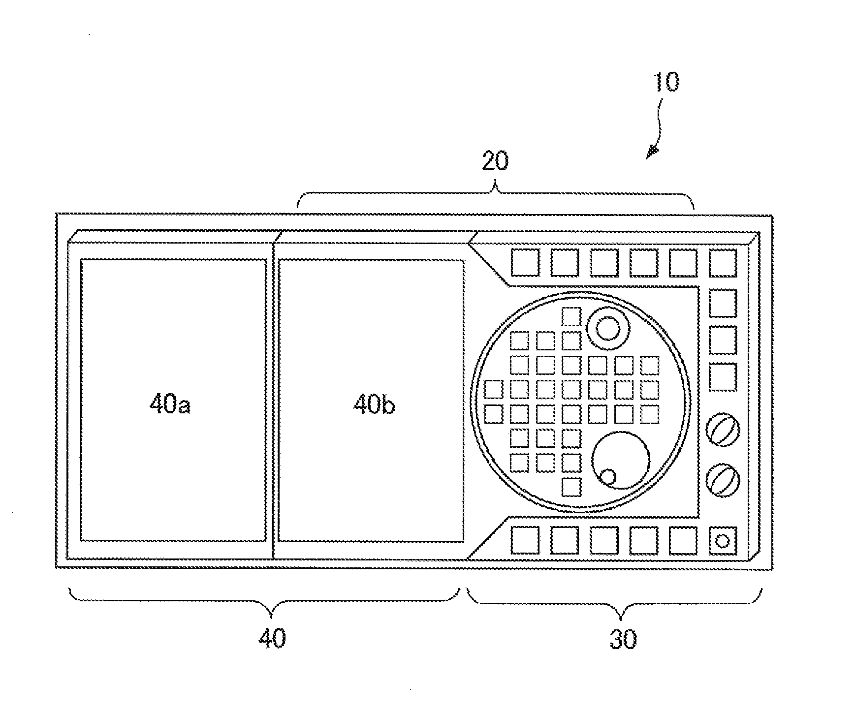
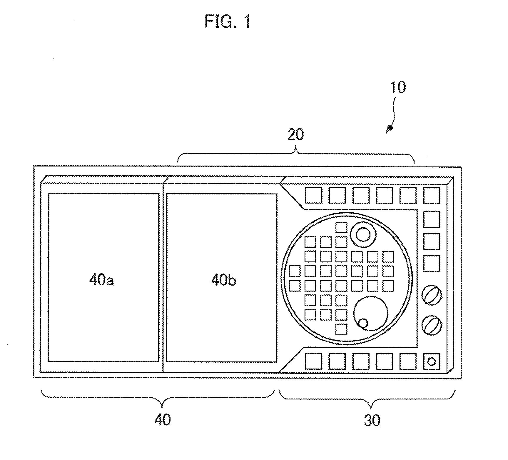
[0037]A machine control panel with a display 10 according to this embodiment includes, as shown in FIG. 1, an operation section 30 and a display section 40 disposed side by side with the operation section 30. The display section 40 is configured from two LCD panels having the same size, i.e., a first display section 40a and a second display section 40b.

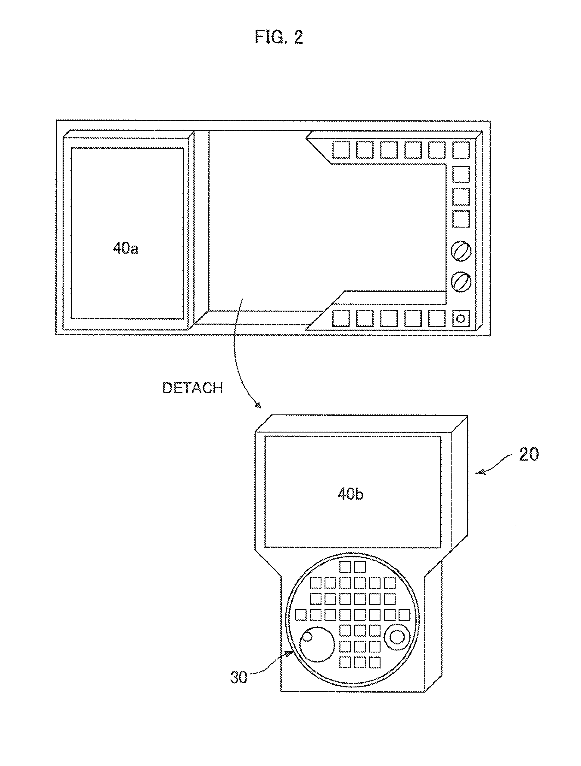
[0038]The first display section 40a and the second display section 40b are disposed side by side on the left and right such that the long sides of the respective panels are in contact with each other as shown in FIG. 1. The first display section 40a is fixed to a main body (a control panel main body) of the machine control panel with the display 10. On the other hand, the second display section 40b configures a detachable section 20 in conjunction with a part of the operation section 30. As shown in FIG. ...

second embodiment

[0061]A machine control panel with a display according to the present invention is explained with reference to FIGS. 5 to 7.

[0062]The machine control panel with the display 10 according to this embodiment includes, as shown in FIG. 5, the operation section 30 and the display section 40 disposed side by side with the operation section 30. The display section 40 is configured from two LCD panels having the same size, i.e., the first display section 40a and the second display section 40b.

[0063]The first display section 40a and the second display section 40b are disposed side by side on the left and right such that the long sides of the respective panels are in contact with each other as shown in FIG. 5. The first display section 40a is fixed to a main body (a control panel main body) of the machine control panel with the display 10. On the other hand, the second display section 40b is configured to be independently detachable from the control panel main body as shown in FIG. 6A in a s...

third embodiment

[0073]A machine control panel with a display according to the present invention is explained with reference to FIG. 8.

[0074]FIG. 8 is a block diagram showing the machine control panel with the display 10 according to the third embodiment of the present invention and the numerical controller 62 of the machine tool 60 to which the machine control panel 10 is connected. In the figure, components same as the components in the block diagram in the first embodiment shown in FIG. 4 are denoted by the same names and explanation of the components is omitted.

[0075]In this embodiment, the graphic control section 108 in the main body side control section 70 in the first embodiment is omitted. Creation of image data performed by the graphic control section 108 in the first embodiment is performed by the CPU 64 of the numerical controller 62. The image data is written in the DRAM 66. The DMA controller 106 of the main body side control section 70 transfers the image data written in the DRAM 66 of...


PUM


Abstract

There is provided a machine control panel with a display connected to a numerical controller of a machine tool. A part of a display section and an operation section are detachable from a main body. When a detachable section configured from the part of the display section and the operation section is detached from the main body, the detachable section is usable as a portable control panel. On the other hand, in a state in which the detachable section is attached to the main body, the display section and another display section fixed to the main body are combined as one screen to perform display.

Description

RELATED APPLICATIONS[0001]The present application claims priority to Japanese Application number 2014-030994, filed Feb. 20, 2014, the disclosure of which is hereby incorporated by reference herein in its entirety.BACKGROUND OF THE INVENTION[0002]1. Field of the Invention[0003]The present invention relates to a machine control panel with a display and, more particularly, to a machine control panel with a display connected to a numerical controller of a machine tool.[0004]2. Description of the Related Art[0005]Conventionally, in numerical controllers that numerically control a machine tool, a control panel including switches, keys, and the like and a display for checking work content for creating and editing a machining program for machine tools and for performing selection and execution of an already-created machining program are provided. In general, the control panel and the display are attached to a power panel cabinet of the machine tool or an exclusive housing for attaching the...

Claims


Application Information

Patent Timeline
Patent Type & Authority Patents(United States)
IPC IPC(8): G06F3/14G06F3/041G05B19/409G06T3/60
CPCG06F3/1423G05B19/409G06F3/041G05B2219/36159G06T3/60B23Q1/0009G09G2340/0407G09G2340/0492G06F1/1626G06F1/1632
Inventor SAKAI, YUTAKAANDO, HIROSHIGE
Owner FANUC LTD
Why Eureka
Try Eureka