Cooling system for an asynchronous rotor

a cooling system and asynchronous rotor technology, applied in the field of squirrel cage rotor, can solve the problems of reducing the effectiveness of such a cooling method, less effective blades on the shorting ring, and more difficult to remove heat from the rotating component such as the rotor, so as to achieve higher electrical resistance, higher electrical resistance of the starting bar, and higher electrical resistance

Inactive Publication Date: 2016-12-06
SIEMENS AG
View PDF26 Cites 5 Cited by
  • Summary
  • Abstract
  • Description
  • Claims
  • Application Information

AI Technical Summary

Benefits of technology

[0015]The invention is based on the knowledge that in a squirrel cage rotor having shorting rings cast onto the end faces, said shorting rings can be used as an excellent means of heat dissipation by casting them directly onto the ends of heat pipes. Said heat pipes, which may be in the form of thermosiphons, penetrate the laminated rotor core substantially axially. They transfer the heat produced in the laminated rotor core to the two axial ends of the rotor. At these ends, they are integrally cast into the shorting rings, thereby enabling practically optimum heat conduction across the contact between the heat pipes and the shorting rings. The shorting rings, which have a large surface area, perform the role of condenser for the heat pipes, and therefore an effective heat cycle is created very simply.
[0024]A particularly high electrical efficiency can be achieved in a hybrid construction in a further advantageous embodiment of the invention by making the shorting bars out of copper, and by arranging cast bars in the first slots, said cast bars filling a residual cross-section that is not filled by the shorting bars in the first slots, wherein the cast bars and the shorting rings are made of aluminum. The copper shorting bars significantly increase the conductivity and hence the efficiency of the squirrel cage rotor. The aluminum melt that fills the residual cross-section mechanically fixes the shorting bars inside the slot in an excellent manner.

Problems solved by technology

It is more difficult, however, to remove the heat from a rotating component such as the rotor.
The blades on the shorting ring become less effective at dissipating heat as the number of poles in a machine increases.
The effectiveness of such a cooling method also reduces with the axial length of the laminated rotor core because it then becomes increasingly difficult to enable sufficient heat removal along the entire rotor core length.

Method used


Image

  • Cooling system for an asynchronous rotor
  • Cooling system for an asynchronous rotor
  • Cooling system for an asynchronous rotor

Examples


first embodiment

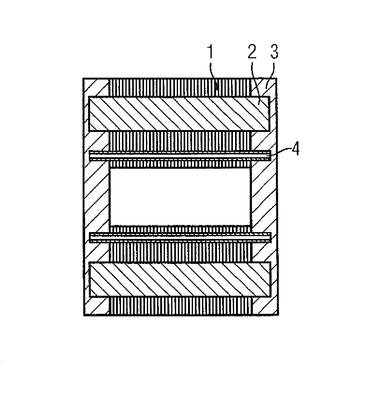
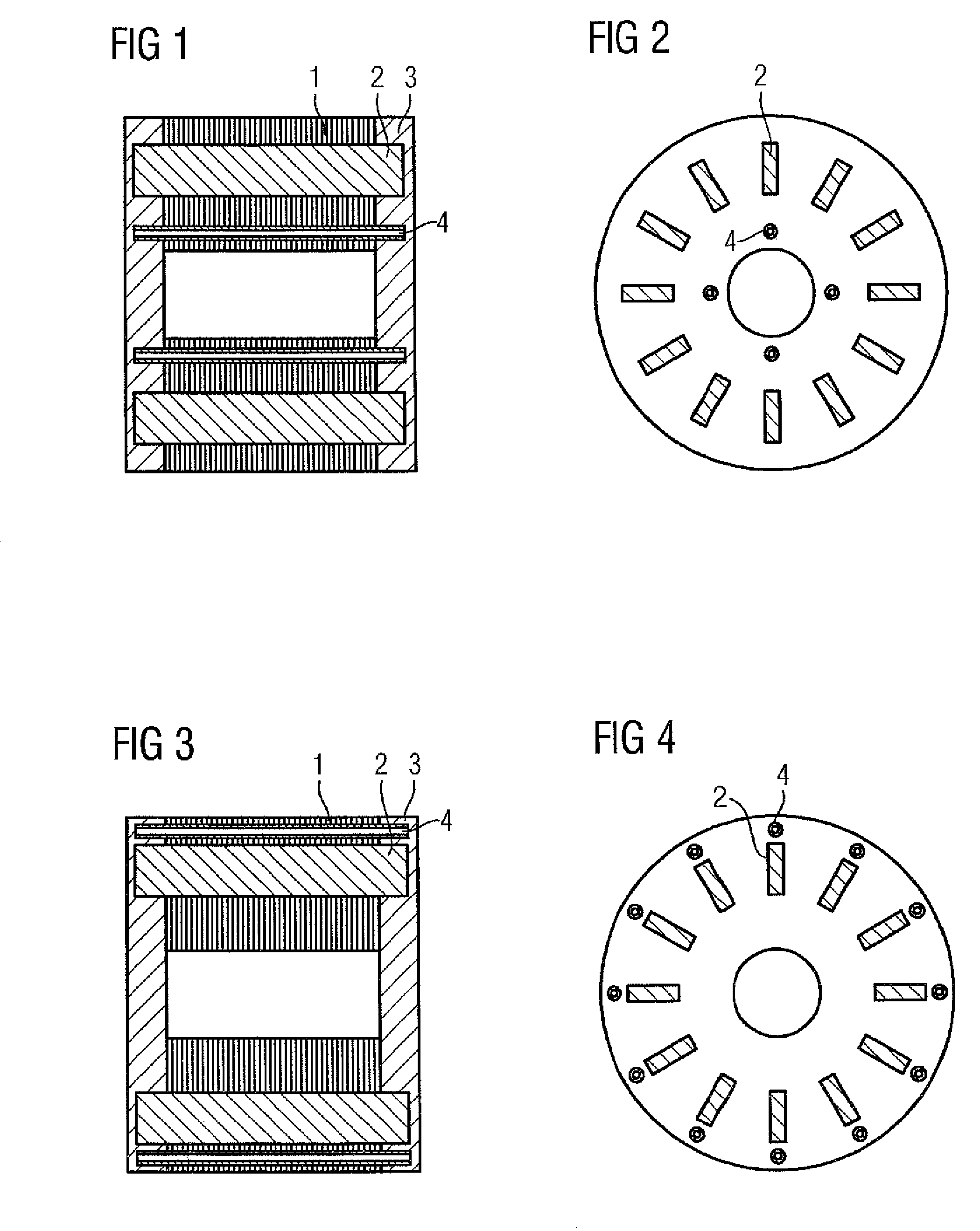
[0036]FIG. 1 shows in cross-section a laminated rotor core 1 containing heat pipes 4. The laminated rotor core 1 is constructed of axially stacked electrical plates that are electrically insulated from one another. This construction reduces iron losses and eddy-current losses in the laminated rotor core 1.

[0037]In addition, the laminated rotor core 1 comprises first slots, in which shorting bars 2 are arranged. In order to achieve a maximum possible electrical efficiency, these shorting bars 2 are made of copper.

[0038]In addition, the laminated rotor core 1 comprises second slots in the form of axial holes, in which the heat pipes 4 are arranged. Viewed in the radial direction of the laminated rotor core 1, the heat pipes 4 and hence the second slots are located further inwards than the shorting bars 2 or the first slots.

[0039]In the manufacture of the squirrel cage rotor shown here, the shorting bars 2 and the heat pipes 4 are first inserted in the relevant slots. Then the laminate...

second embodiment

[0043]For example, FIG. 3 shows in cross-section a laminated rotor core 1 containing heat pipes 4. Like the embodiment of FIG. 1, first slots for holding shorting bars 2 are provided and second slots in the form of an axial hole for holding the heat pipes 4 are again provided here. In this embodiment, the second slots and hence the heat pipes 4 are arranged towards the outside viewed axially, i.e. in the vicinity of the outer sheath. The shorting bars 2, which are again made of copper in this case, are located towards the inside viewed in the radial direction of the rotor, i.e. nearer the rotor shaft. In this embodiment, the heat pipes 4, which are likewise made of copper, are used as starting bars for the asynchronous rotor. Their cross-sectional area is significantly less than that of the shorting bars 2. Hence the electrical resistance that the heat pipes present between the two shorting rings is significantly higher than that of the shorting bars 2.

[0044]Owing to the skin effect...

third embodiment

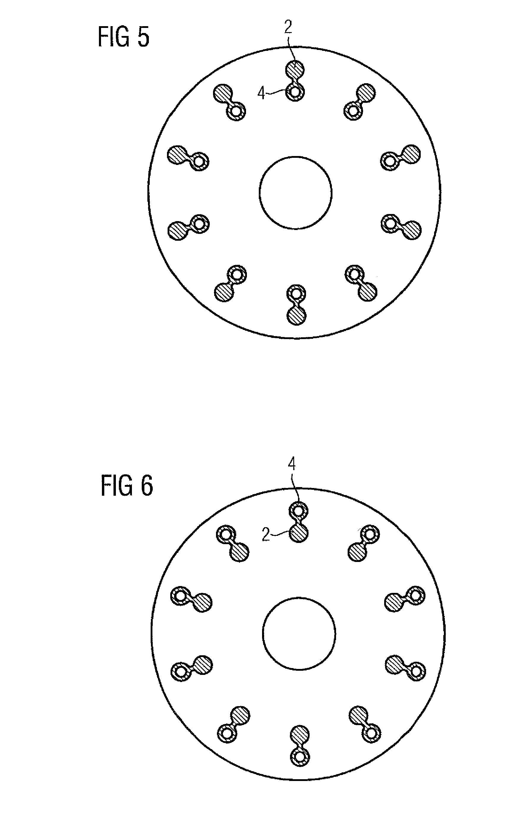
[0046]FIG. 5 shows a laminated rotor core containing heat pipes 4. In this case, both the heat pipes 4 and the shorting bars 2 are arranged in “double-bar slots”, i.e. in this arrangement the first slot, which is provided for the shorting bar 2, is connected via a thin connecting bridge to the second slot, which is provided for the heat pipe 4. The drawing shows a cross-section through the laminated rotor core and hence through the shorting bars 2 and the heat pipes 4. Viewed radially, the heat pipes 4 are arranged further inwards than the shorting bars 2. Such an arrangement makes sense particularly when the electrical resistance that the heat pipes 4 present between the two shorting rings is less than the electrical resistance that the shorting bars 2 present between the two shorting rings.

[0047]Normally, the cross-sectional area of the heat pipes 4 is less than that of the shorting bars 2, which are of solid construction. If, however, aluminum shorting bars, for instance made fro...


PUM

PropertyMeasurementUnit
electricallyaaaaaaaaaa
electrical resistanceaaaaaaaaaa
centrifugal forceaaaaaaaaaa

Abstract

A cage rotor for an synchronous machine includes a laminated rotor core, shorting bars arranged inside the laminated rotor core, shorting rings which are cast onto the laminated rotor core and which electrically interconnect the shorting bars to front sides of the laminated rotor core, and heat pipes introduced into the laminated rotor core in the axial direction such that they protrude onto the front side from the laminated rotor core and protrude into the shorting rings.

Description

CROSS-REFERENCE TO RELATED APPLICATIONS[0001]This application is the U.S. National Stage of International Application No. PCT / 2010 / 063275, filed Sep. 10, 2010, which designated the United States and has been published as International Publication No. WO 2011 / 032887 and which claims the priority of European Patent Application, Serial No. 09170558.2, filed Sep. 17, 2009, pursuant to 35 U.S.C. 119(a)-(d).BACKGROUND OF THE INVENTION[0002]The invention relates to a squirrel cage rotor for an asynchronous machine, said rotor comprising a laminated rotor core having shorting rings which are cast onto the end faces of the laminated rotor core. The invention is concerned in particular with the cooling system of such a squirrel cage rotor.[0003]In addition, the invention relates to a method for producing such a squirrel cage rotor in which a corresponding cooling system is provided.[0004]In order to increase the efficiency of an electrical machine, various cooling techniques are used in which...

Claims


Application Information

Patent Timeline
Patent Type & Authority Patents(United States)
IPC IPC(8): H02K9/20H02K15/00H02K1/32H02K17/16H02K17/18
CPCH02K9/20H02K1/32H02K15/0012H02K17/165H02K17/18Y10T29/49009H02K9/225
Inventor BUTTNER, KLAUSKIRCHNER, KLAUS
Owner SIEMENS AG
Why Eureka
Try Eureka