Boom stand stacking counterweights

a technology of counterweights and boom stands, applied in the direction of machine supports, stand/trestles, mouthpiece/microphone attachments, etc., can solve the problems of not being able to be used or stored in close arrangement, the base is not easily transported, and the boom is prone to sagging, so as to prevent the tipping of the vertical support, the effect of preventing the sagging and preventing the sagging

Active Publication Date: 2016-12-06
ROBERTS JEFFREY A +1
View PDF21 Cites 6 Cited by
  • Summary
  • Abstract
  • Description
  • Claims
  • Application Information

AI Technical Summary

Benefits of technology

[0027]It is the principal object of the present invention to stabilize a boom, both to aid in the prevention of tipping a vertical support and to aid in the prevention of the boom sagging if the connection between boom and vertical support weakens or loosens, by providing a counterweight that creates an equal and opposite torque to that created by a microphone or other device supported by the boom. An additional object of the present invention is to provide this stability through a counterweight that is quickly and easily customizable, intuitive, and relatively compact. A further object of the present invention is to provide a variable counterweight that can be easily manually attached and detached in stages to provide a variable amount of weight adjacent to a boom end. Another object of the present invention is to provide a large grasping surface area so as to enable nearly all persons to manually grasp and rotate individual weights with sufficient force to secure them to the boom and to other weights, without tools and still avoiding the risk of extraneous rattle or vibration that might interfere with the operation of an electroacoustic device. Yet another object of the invention is to provide a way to manually stack counterweights together in a manner that is free of acoustic vibration, secure, and which permits manual separation even after exposure to acoustic and other vibrations at any angle of orientation of the boom.

Problems solved by technology

Unfortunately, in the prior art this often led to the use of a large and very massive base, typically of disc, slightly domed, or similar shape.
Such a base is not readily transported, nor can it be used or stored in close arrangement with other bases.
Consequently, it is not possible to tightly and compactly arrange, use or store a plurality of similar stands.
Unfortunately, these stands also have drawbacks.
Long legs in turn form a serious hazard for anyone passing near to the boom stand.
In the event a boom stand is accidentally knocked over, the item supported thereon may be destroyed.
In the case of the performing arts, the microphones that are supported thereon may cost thousands of dollars to replace.
Furthermore, the disruption to a performance when a stand is accidentally toppled is highly undesirable.
Consequently, there are trade-offs that have been required with many of the prior art boom stands in either portability or stability that are undesirable.
Either the stand is light and unstable, light and in the way and prone to being accidentally toppled, or heavy and difficult to handle, move about, and store.
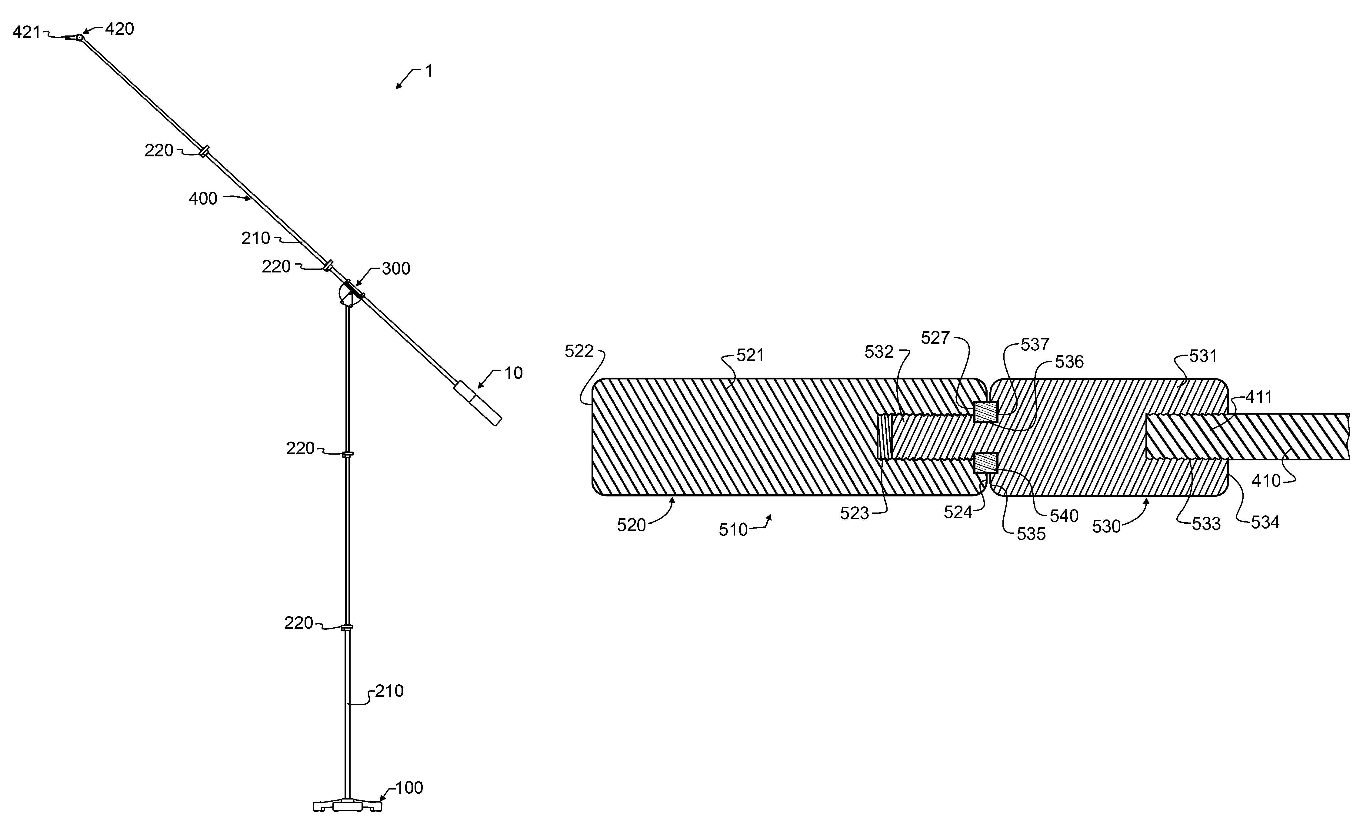
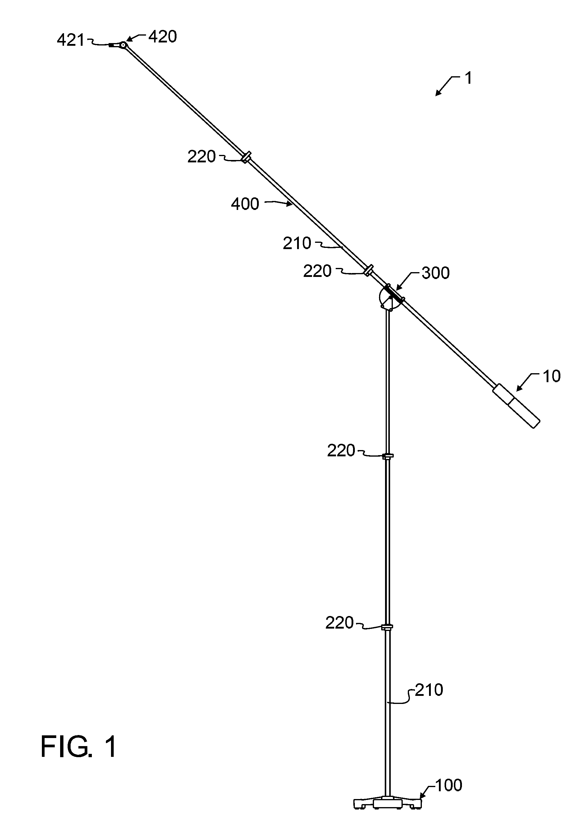
Even where the vertical support is stable enough to support an unbalanced device some horizontal distance from the vertical support, another challenge arises in the coupling between boom and vertical support.
In many of the prior art stands the connection between the boom and the vertical support can weaken or slip, causing the boom to lower on the side with the device.
This sagging leads to undesirable movement away from the musician or instrument, which can lead to complete loss of adequate signal coming from this microphone or to a loss of selectivity of sound being received by the microphone.
This sagging arises due to an inadequate coupling between boom and stand.
The end result of this inadequate coupling between boom and stand is movement of the boom, which may in turn lead to the device being located in a position not balanced directly over the vertical support, and therefore require all too frequent manual readjustment and alignment.
Additionally, this imbalance provides a certain amount of risk of tipping the vertical support, which can lead to destruction of sensitive microphones, as well as harm or damage to surrounding equipment and people.
As a result, and as is known in the industry, even minor forces of only a few pounds at the end of the boom overcome the resistance at the knuckle, since these few pounds require thousands of pounds of force at the knuckle to stop such rotation.
The few pounds of force cause the boom to realign undesirably.
However, there are many stands that have already been produced and placed into service that do not have the features found in the stands designed in accord with the present inventor's patents.
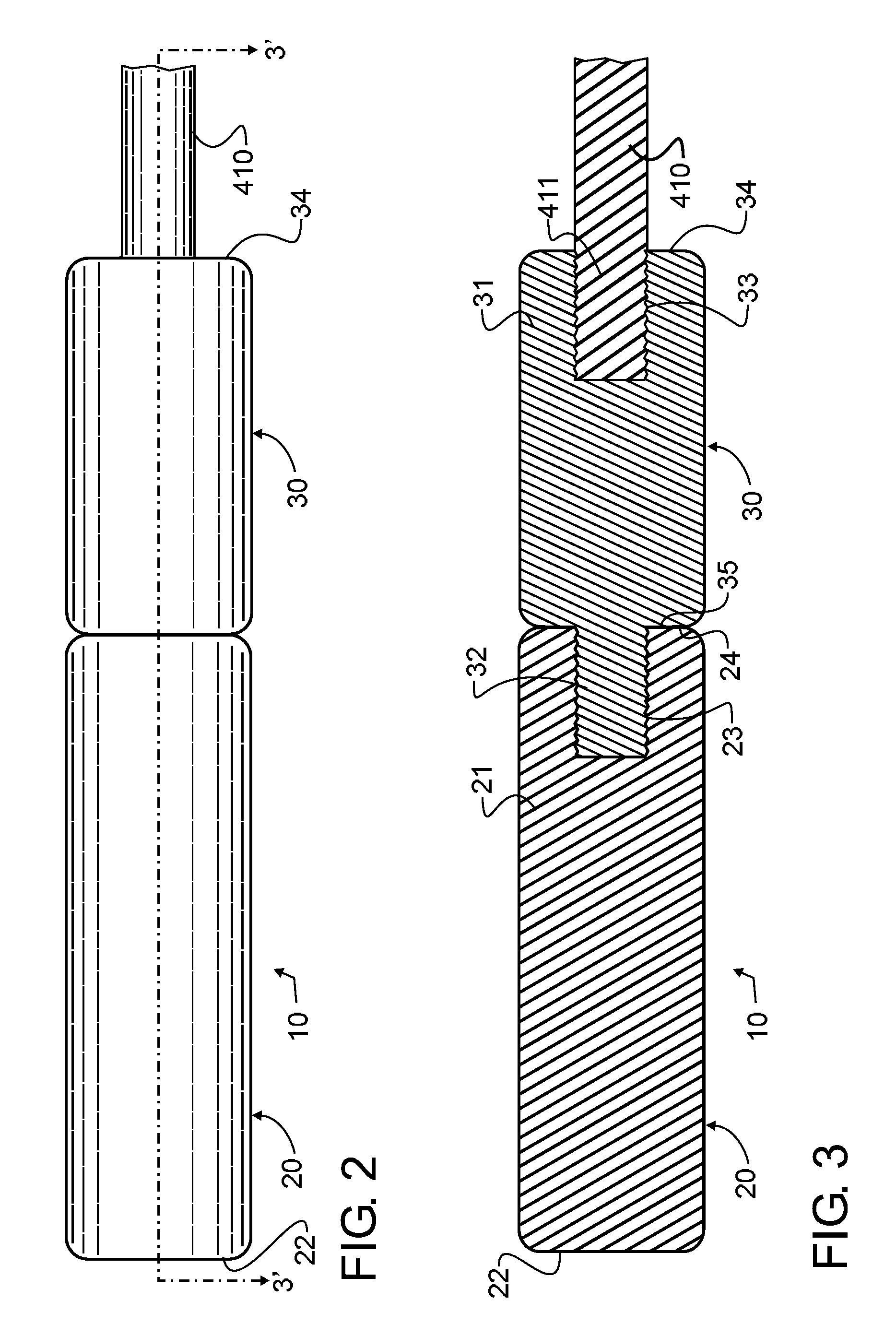
However, with this counterweight comes a new set of challenges.
Since the weight is intended to slide along the boom, and since the boom will generally not be a perfect cylinder, there must also be some space or gap between the inside bore of the weight and the outside diameter of the boom to accommodate these variances.
This also means that the weight cannot fit tightly onto the boom, except for by the use of a set screw.
Over time, the set screw will damage the boom, and will also tend to loosen, just as the coupling between boom and stand tends to loosen.
As a result, this type of weight loses efficacy, and may also damage or destroy the boom.
If the set screw loosens, there will be a great propensity for acoustic vibration, which can destroy the function of the microphone and stand.
Because of the limited engaging surfaces, which comprise the tip of the set screw and a small line of contact directly opposite of the set screw tip, there may also be a tendency in some stands to develop destructive acoustic vibrations even when the set screw is secured.
As a result, these types of weights are normally affixed once and often never adjusted again.
Undesirably, this weight is relatively complex, thereby requiring greater cost and incorporating a greater chance of failure or undesirable resonances, and still provides only for a boom with or without the single weight.
However, there is nothing to load or lock the threads, meaning the device will tend to spin about the threads, and self-adjust.
In addition, since there is no solid connection between the weight and the boom, the connection there between will be prone to vibrating undesirably.
However, these booms have very different requirements and objectives than those required for an electroacoustic device.
These weights screw over a threaded shaft, but the weights are free to vibrate against each other and the shaft, making this apparatus completely unacceptable for use with an electroacoustic device.
The cable will create an undesirable resonance at a frequency determined by the cable length and tension, will be awkward to transport, and may be dangerous if accidentally snagged and swung about.

Method used


Image

  • Boom stand stacking counterweights
  • Boom stand stacking counterweights
  • Boom stand stacking counterweights

Examples


Embodiment Construction

[0037]Manifested in the preferred embodiment, the present invention provides a boom stand 1 which is adapted to support one or more of a variety of known devices thereon, including but not solely limited to an electroacoustic device such as a microphone. More specifically, but not limited thereto, microphones, cameras, lights, medical equipment, and many other devices may be supported therefrom. For reasons to be explained herein below, the support of sensitive electrical or electronic equipment is most preferred, especially pertaining to microphones, but the application of the present invention is not solely limited thereto and is instead contemplated by the present inventor to have other applications as well.

[0038]Boom stand 1 includes a base 100 which is designed to support boom stand 1 upon a floor or other surface. Most preferably, though not an absolute requisite, the floor or other surface will be relatively planar or flat, at least in the region adjacent to base 100. This pe...


PUM


Abstract

A boom stand adapted to support an electroacoustic device is constructed from a base, pivotal boom, stand elevating the pivotal boom, and a stacking counterweight. The stacking counterweight includes a terminal weight having a generally cylindrical body longitudinally terminated with a threaded coupler adapted to operatively couple with a threaded coupler on the boom, while aligning the terminal weight longitudinally co-axially with the boom. One or more medial weights having a generally cylindrical body and appropriate threaded couplers can be inserted between the boom and terminal weight. Each of the medial and terminal weights are preferably shaped to be adequately grasped by a person's palm and finger portion of a hand clasping about the longitudinal axis, and are thereby adapted to operatively permit manual rotation about their longitudinal axes.

Description

CROSS REFERENCE TO RELATED APPLICATIONS[0001]This application is a Continuation-In-Part of U.S. patent application Ser. No. 14 / 472,964 filed Aug. 29, 2014 and co-pending herewith, which in turn claims the benefit under 35 U.S.C. 119(e) of U.S. provisional patent application Ser. No. 61 / 871,388 filed Aug. 29, 2013, both of like title, the contents of each which are incorporated herein by reference in entirety.BACKGROUND OF THE INVENTION[0002]1. Field of the Invention[0003]This invention pertains generally to electrical audio signal processing systems and devices, and more particularly to electro-acoustic audio transducers such as housed microphones that are supported upon a boom stand and counterbalanced by stable and acoustically neutral counterweights. In a most preferred manifestation, the present invention relates to acoustically inactive counterweights that are readily manually attached and detached from booms on an electro-acoustic microphone stand.[0004]2. Description of the R...

Claims


Application Information

Patent Timeline
Patent Type & Authority Patents(United States)
IPC IPC(8): F16M11/18F16M11/10H04R1/08
CPCH04R1/08F16M11/10F16M11/18F16M11/2021F16M11/28F16M2200/044
Inventor ROBERTS, JEFFREY A.ROBERTS, DAVID M.
Owner ROBERTS JEFFREY A
Why Eureka
Try Eureka