Lid body, package, electronic apparatus, moving object, and method for manufacturing package

a technology of electronic equipment and packaging, applied in the field of packaging, electronic equipment, moving objects, and manufacturing methods of packages, can solve problems such as sealing failur

Active Publication Date: 2016-12-06
SEIKO EPSON CORP
View PDF29 Cites 0 Cited by
  • Summary
  • Abstract
  • Description
  • Claims
  • Application Information

AI Technical Summary

Benefits of technology

[0013]According to this application example, since the mark has the plurality of recognition areas where the recognition of the position can be carried out, a rotational misalignment of the lid body can be calculated and the detection accuracy of the position of the groove portion can be enhanced further. Therefore, the likelihood of a sealing failure of the groove portion can be reduced.Application Example 4
[0017]According to this application example, since the marks are arranged in the areas on both sides of the groove portion, a long spacing can be provided between the marks and the detection accuracy of the position of the groove portion is enhanced. Therefore, the likelihood of a sealing failure of the groove portion can be reduced.Application Example 6
[0021]According to this application example, the spacing between the centers of the marks with which a misalignment in the rotating direction is determined and the first imaginary straight line is longer than the distance between the second imaginary straight line passing through the center of each of the marks and the point of intersection between the first imaginary straight line and the outer peripheral surface on the side where the groove portion is provided, as viewed in a plan view. Therefore, the detection accuracy in the rotating direction can be maintained even if there are some positional recognition errors of the marks, and the detection accuracy of the position of the groove portion is enhanced. Thus, the likelihood of a sealing failure of the groove portion can be reduced.Application Example 8
[0035]According to this application example, the lid body having the mark provided on the second surface is used, and the position of the groove portion on the first surface (back side) can be calculated on the basis of the mark. Thus, as the position of the groove portion is specified, a misalignment at the time of sealing the groove portion can be prevented and the occurrence of a sealing failure (an air leak failure) can be reduced. Also, since the mark will not melt away even if the joining area is melted by welding, the position of the groove portion can be detected securely and appropriately.

Problems solved by technology

Consequently, there is a risk that the sealing in the unsealed area may be insufficient, causing a sealing failure (an air leak failure).

Method used


Image

  • Lid body, package, electronic apparatus, moving object, and method for manufacturing package
  • Lid body, package, electronic apparatus, moving object, and method for manufacturing package
  • Lid body, package, electronic apparatus, moving object, and method for manufacturing package

Examples


first embodiment

[0051]First, as a first embodiment of the invention, a package having a lid body, an oscillator as an electronic device using the package, and a method for manufacturing the oscillator will be described with reference to FIG. 1 to FIGS. 6A to 6D.

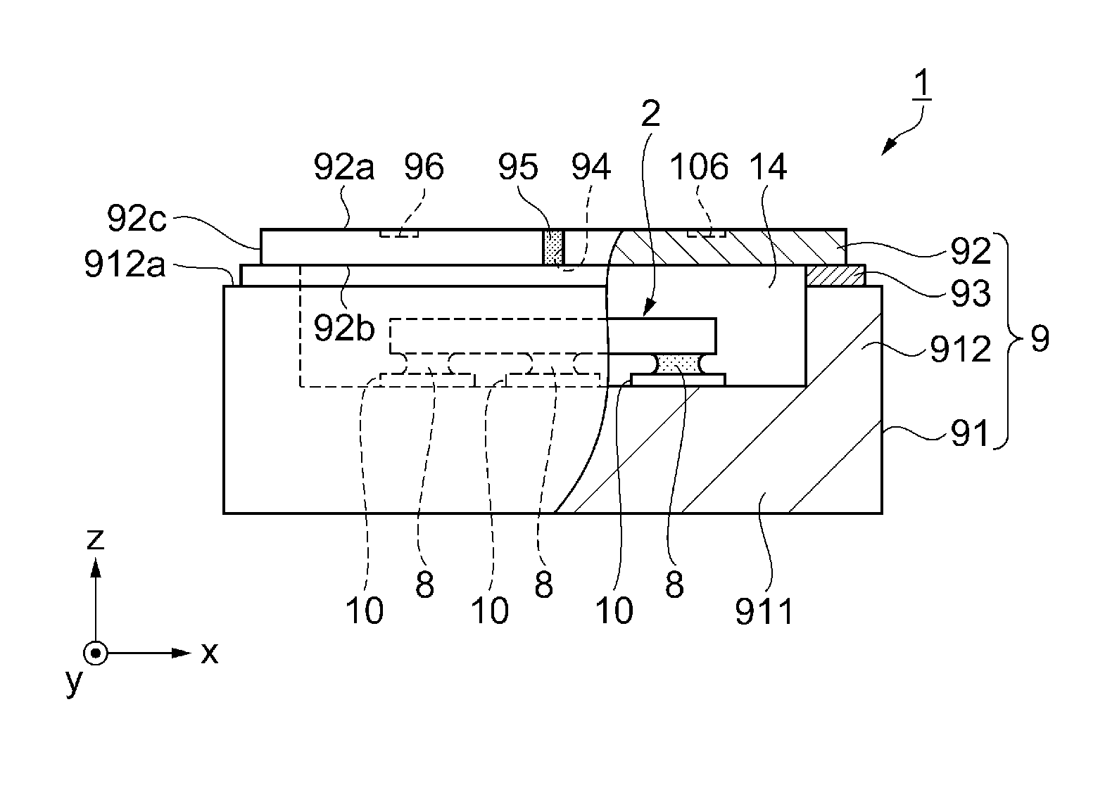
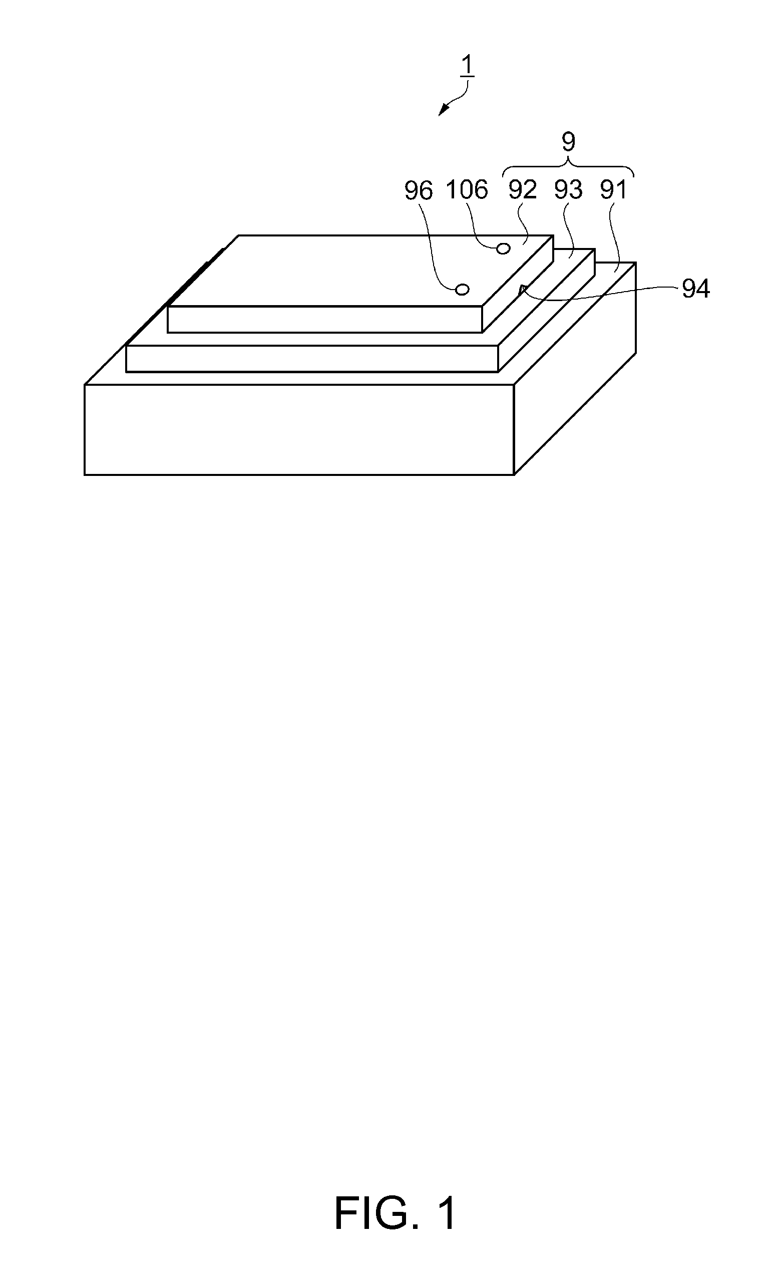
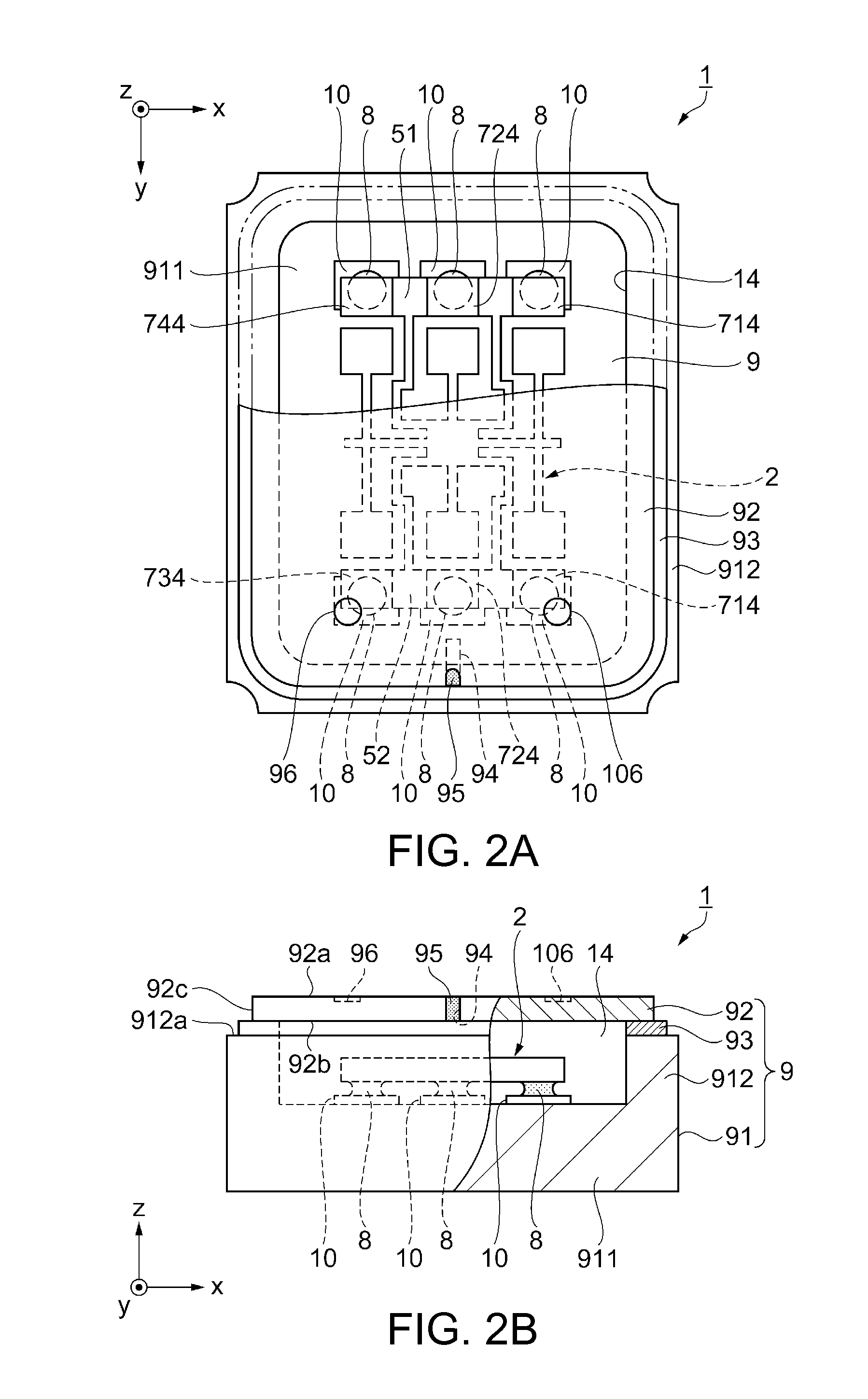
[0052]FIG. 1 is a schematic perspective view showing an oscillator as an electronic device using a lid body according to the invention. FIGS. 2A and 2B schematically show the oscillator according to the first embodiment. FIG. 2A is a plan view. FIG. 2B is a front cross-sectional view. FIG. 3 is a plan view showing a gyro element as an electronic component of the oscillator shown in FIGS. 2A and 2B. FIGS. 4A and 4B show an example of a lid body (lid) used for the oscillator. FIG. 4A is a plan view. FIG. 4B is a front cross-sectional view. FIGS. 5A to 5D are front cross-sectional views schematically showing the manufacturing process of the oscillator. FIGS. 6A and 6D show the joining state between a lid and a base. FIGS. 6A and 6C are plan vie...

modification 1

[0093]Referring to FIG. 7A, a modification 1 of the mark will be described. As the mark in the modification 1, a single first mark 96 is provided. The groove 94 is provided on the first surface (not shown) of the lid 92, and the first mark 96 is provided on the second surface 92a having a top-bottom relation with the first surface. The first mark 96 is provided on the second surface 92a of the lid 92 and at a position that does not overlap with the outer peripheral surface of the second surface 92a, that is, a position that overlaps with the groove 94, as viewed in a plan view.

[0094]As the first mark 96 is provided in this manner, the position of an end of the groove 94 can be directly recognized with the first mark 96. Therefore, the detection accuracy of the groove position is enhanced and the position accuracy of the position P3 where the laser beam 98 is directed can be improved. Thus, sealing failure of the groove 94 can be reduced.

modification 2

[0095]Referring to FIG. 7B, a modification 2 of the mark will be described. As the mark in the modification 2, a single mark 96a is provided. The groove 94 is provided on the first surface (not shown) of the lid 92, and the mark 96a is provided on the second surface 92a having a top-bottom relation with the first surface. The mark 96a is provided on the first imaginary straight line C which bisects the lid 92, connecting the center of the width of the groove 94 in the direction (x-axis direction in the illustration) intersecting with the extending direction (y-axis direction in the illustration) of the imaginary line (not shown) connecting the groove 94 and the center part of the second surface 92a, and the center G of the second surface 92a, as viewed in a plan view. The mark 96a is substantially rectangular (in this example, a rectangle) and extends on the first imaginary straight line C as the longitudinal direction thereof. The mark 96a has a first recognition area A1 and a seco...


PUM


Abstract

A lid body includes: a first surface; a second surface having a top-bottom relation with the first surface; an outer peripheral surface connecting the first surface and the second surface; a groove provided in the first surface from the outer peripheral surface toward an interior of the first surface; and first and second marks arranged at positions that do not overlap with an outer peripheral edge of the second surface in a plan view.

Description

BACKGROUND[0001]1. Technical Field[0002]The present invention relates to a lid body, a package, an electronic apparatus, a moving object, and a method for manufacturing a package.[0003]2. Related Art[0004]Recently, as the use of portable electronic apparatuses is becoming widespread, a reduction in the size, weight and cost of such electronic apparatuses is increasingly demanded. Therefore, a reduction in size and cost while maintaining high accuracy is increasingly demanded with respect to electronic components used in the electronic apparatuses as well. Particularly, in an oscillation device having an oscillation element housed within a package, the oscillation characteristic is maintained by keeping the space housing the oscillation element in an airtight condition. Therefore, various sealing techniques for this are proposed.[0005]For example, in the joining method disclosed in JP-A-2008-153485, a lid body (lid) of a container that covers an opening of a space housing an oscillat...

Claims


Application Information

Patent Timeline
Patent Type & Authority Patents(United States)
IPC IPC(8): H01L41/053H03H9/10H03B5/30H01L21/50H01L23/544H01L23/04H05K5/02H05K5/06
CPCH05K5/0239H01L21/50H01L23/04H01L23/544H01L41/053H03B5/30H03H9/10H05K5/069H01L2223/5442H01L2223/54426H01L2223/54486H01L2224/16225H01L2924/16195H05K5/03H10N30/88
Inventor MATSUZAWA, JUICHIRO
Owner SEIKO EPSON CORP
Why Eureka
Try Eureka