Dispensed liquid measurement device

a liquid measurement and liquid technology, applied in the direction of liquid/fluent solid measurement, instruments, laboratory glassware, etc., can solve the problems of introducing errors in gravimetric analysis, affecting the accuracy of measurement, and high cost of the machine necessary for this method, so as to achieve accurate determination, the effect of reusable or disposabl

Active Publication Date: 2016-12-13
FORWARD BIOTECH
View PDF16 Cites 3 Cited by
  • Summary
  • Abstract
  • Description
  • Claims
  • Application Information

AI Technical Summary

Benefits of technology

[0017]The present invention provides a measuring device, which includes a capillary and a well for dispensed liquid, positioned such that the inlet end of the capillary can contact liquid placed in the well. The entire measuring device, or just the capillary, could be disposable or reusable. Markings on the capillary or on the measuring device can correspond with the volume inside the capillary. The liquid dispensed into the well, and subsequently drawn into the capillary, can be accurately determined, by comparing the location of the liquid / air interface meniscus with the markings. Alternatively, sensors could determine the location of the meniscus or multiple meniscuses.

Problems solved by technology

The machines necessary for this method are fairly expensive.
The calibration process is arduous, time consuming, and prone to inaccuracies, particularly at small volumes where evaporation of water and the propensity for water to adhere to plastics can introduce error.
At these lower volumes, the movement of air currents across the pan of a sensitive scale, or slight vibrations transmitted through a building's structure, can also introduce error in gravimetric analyses.
While others have developed methods for collecting selected volumes of liquids using the geometry of the capillary-type device, such as Kenney in U.S. Pat. No. 6,531,098 and Karg et al. in U.S. Pat. No. 8,080,218, no one has invented an easy method of determining whether a desired volume of liquid is accurately dispensed.

Method used


Image

  • Dispensed liquid measurement device
  • Dispensed liquid measurement device
  • Dispensed liquid measurement device

Examples


Embodiment Construction

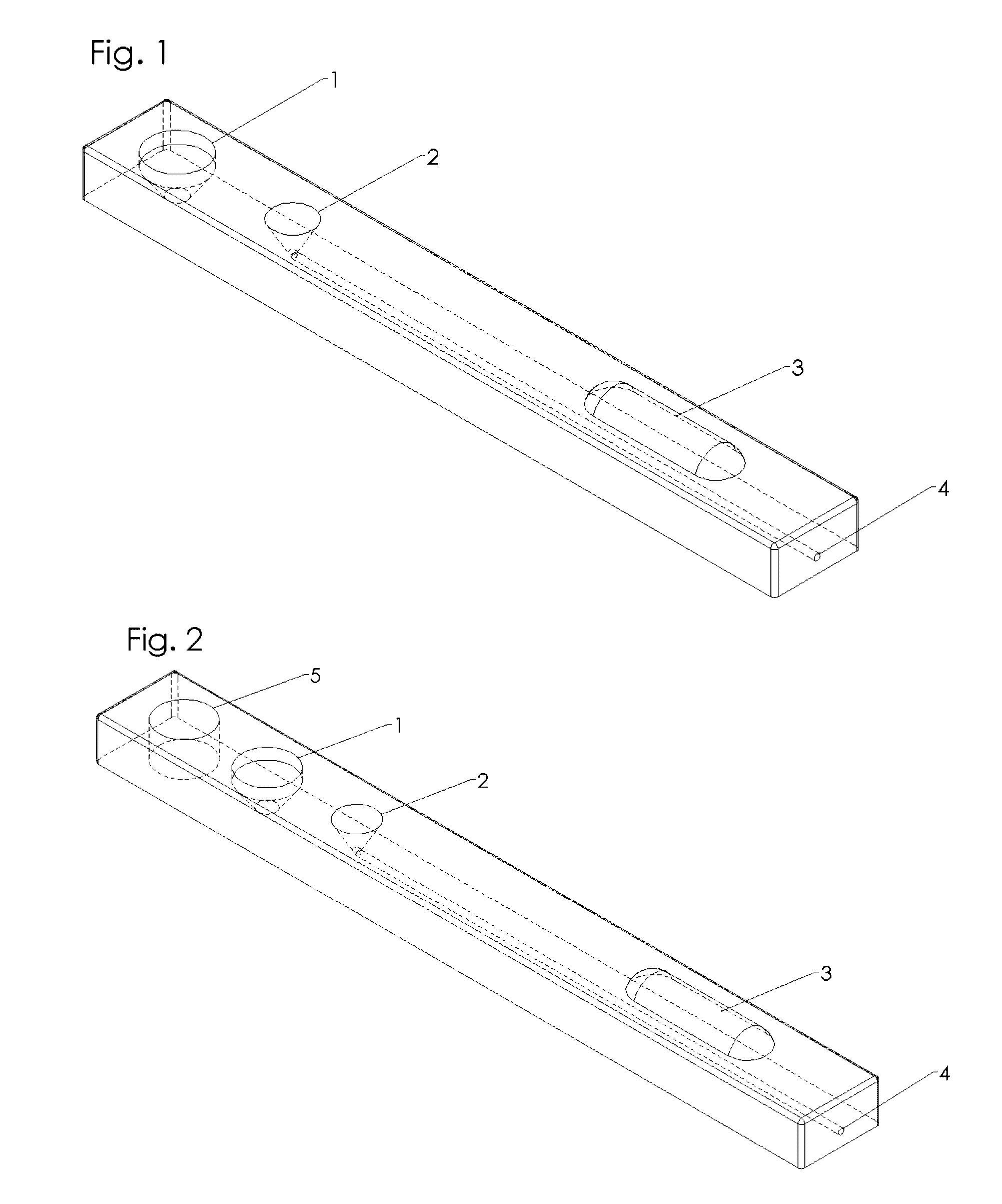
[0035]Referring now to the invention in more detail, in FIG. 1 there is shown a measurement device containing a capillary (4) extending from the funnel shaped well (2) toward and beyond a viewing window, which may be a magnifying lens (3). The proximal end of the capillary is the inlet end by the funnel shaped well. The fluid to be dispensed can be collected from the reservoir (1) by a dispensing device such as a pipette or micropipettor. This fluid can contain a dye for better viewing, and the reservoir may be filled with a sufficient amount of fluid or dye and sealed during manufacture of the measurement device. FIG. 2 shows an optional additional reservoir (5) for a secondary liquid. This secondary liquid can be used to fill the funnel shaped well (2) so long as the secondary liquid is not attracted to the capillary. The secondary liquid can then be used to prevent attraction between the fluid being measured and the measuring device material.

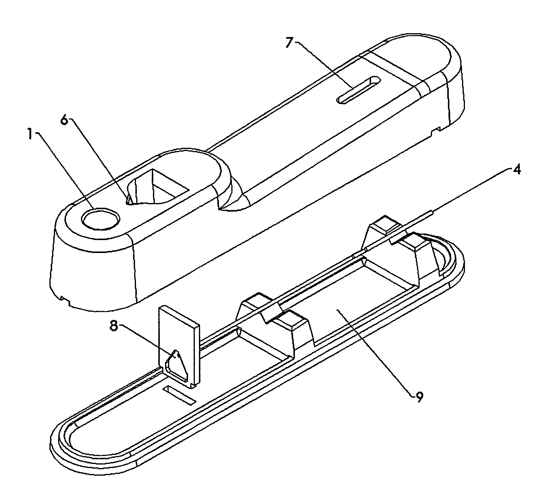
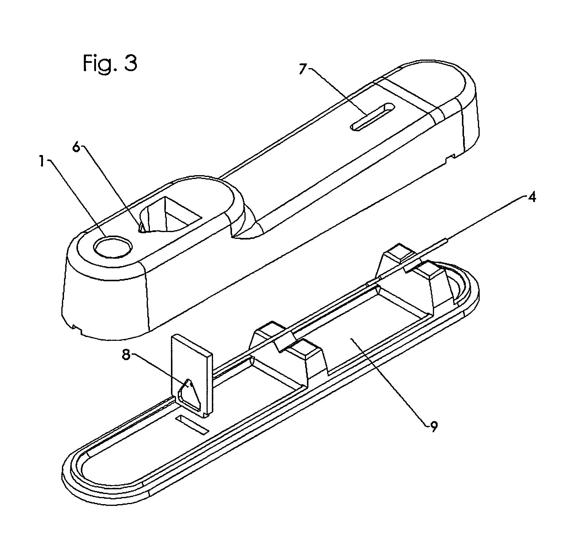
[0036]In FIG. 3 there is shown a measu...


PUM


Abstract

A measurement device containing one or more capillaries to measure the volume of a dispensed fluid and determine the volumetric accuracy of the dispensing device. The measurement device can contain a reservoir containing the fluid to be measured and there may be an additional reservoir for a secondary fluid. A viewing window is necessary to complete a manual measurement and may include a magnifying lens. The liquid well by the capillary inlet may be shaped such that the measurement fluid is directed toward the capillary. The well may have features designed to position the dispensing device toward the capillary, or to position the well proximal to the capillary after it is filled. The well may also have surfaces or coatings which attract or do not attract various types of substances. The measurement device may interface with sensors to output measurement data.

Description

REFERENCE TO SEQUENCE LISTING, A TABLE, OR A COMPUTER PROGRAM LISTING COMPACT DISK APPENDIX[0001]Not ApplicableFIELD OF THE INVENTION[0002]The present invention is in the technical field of fluid measurement and testing.[0003]More particularly, the present invention is in the technical field of calibrating or verifying the calibration of fluid dispensing devices. Some examples of these devices are, but are not limited to: pipettors, multi-channel pipettors, or automated dispensers. The present invention may be used to measure the accuracy of the device for aspirating and dispensing a specific volume of liquid. In particular, the field of the invention relates to the confirmation that the device is correctly calibrated such that the volume of liquid aspirated and dispensed is accurate and repeatable within the error limits determined by the manufacturer of the device and international standards such as ISO 17025.BACKGROUND OF THE INVENTION[0004]Liquid handling pipettors are an essent...

Claims


Application Information

Patent Timeline
Patent Type & Authority Patents(United States)
IPC IPC(8): G01F25/00B01L3/02B01L3/00
CPCB01L3/0293B01L3/5027G01F25/0084B01L2200/148B01L2300/028B01L2300/0838B01L2400/0406G01F25/0092G01F17/00
Inventor GLASGOW, IAN K.KOLB, BRIANHABURA, ANDREA
Owner FORWARD BIOTECH
Why Eureka
Try Eureka