Device for securing floating bodies

a floating body and body technology, applied in the direction of mooring equipment, pontoons, dry-docking, etc., can solve the problems of substantial damping of movements and inability to compensate, and achieve the effect of reducing buoyant forces

Active Publication Date: 2016-12-13
DUAL DOCKER
View PDF17 Cites 1 Cited by
  • Summary
  • Abstract
  • Description
  • Claims
  • Application Information

AI Technical Summary

Benefits of technology

[0009]A device, in particular a floating dock, is provided by the invention, which still lies comparatively calmly on the water even in the event of extremely difficult conditions with respect to wind and waves. This is in particular because the framework-like underwater construction is arranged at a distance under the path construction and thus comes to rest in calmer water depths. The wave amplitudes and therefore the forces acting on the underwater structure or on the floating dock decrease with increasing water depth. The underwater structure lying in calmer waters is connected to the path structure associated with the water surface via pendulum supports, which are only to absorb traction and compression forces per se and which hold the framework-like underwater structure and the path structure at a defined distance to one another. To reduce and damp movements in the path structure, it is braced with the underwater structure via traction means, in particular cables, chains, or the like. Underwater structure and path structure are connected under pre-tension to the traction means, such that a certain compensation movement of the floating dock is possible, but free movements of the two structures, i.e., the path structure and the underwater structure, in relation to one another are absorbed or prevented. This causes substantial damping of movements in the path structure resting on the water surface, whereby nearly similar conditions are provided for the floating dock as for a fixed dock anchored on pylons, for example, which cannot compensate for tidal range, however. A floating dock implemented according to the invention therefore lies, in the event of appropriate embodiment, approximately as calmly as a fixed dock in unsteady conditions.
[0011]In the event of concern about particularly large loads to be dissipated, it is advantageous to have the holding trees engage at one end on the framework-like underwater structure, which is optionally widened transversely to the dock toward the landing body, and at the other end on the landing body. As already mentioned, the underwater structure only executes movements of substantially lower amplitude, if any at all, than a floating body which floats freely on the surface would do. However, this also means that the forces to be dissipated via the underwater structure into the landing body, for example, the pier, are less and extreme load spikes can therefore be avoided.
[0012]The framework-like underwater structure can widen in this case toward the landing body, which means that the underwater holding trees can be arranged at a greater distance to one another, whereby in turn the forces to be transmitted via the holding trees are reduced, since the distance of the holding trees to the floating dock longitudinal axis is enlarged and any possible transverse forces acting on the dock therefore also cause lesser perpendicular forces in the holding trees.
[0013]In particular, it is advantageous if the framework-like underwater structure has a width which protrudes beyond the path width. Particularly stable floating dock systems may therefore be provided, wherein a sufficient amount of free space for docked floating bodies is provided if the underwater structure is arranged appropriately deeply below the water surface. In addition, underwater structure and path structure can therefore advantageously be mutually braced.
[0016]The buoyant elements are typically associated with the path structure. To reduce the buoyant forces in the region of the water surface, for the above-mentioned reasons, at least a part of the buoyant elements can be designed as part of the framework-like underwater structure. For example, individual ribs of the underwater structure can be tubes which are closed watertight and filled with air, foam, or the like.

Problems solved by technology

This causes substantial damping of movements in the path structure resting on the water surface, whereby nearly similar conditions are provided for the floating dock as for a fixed dock anchored on pylons, for example, which cannot compensate for tidal range, however.

Method used


Image

  • Device for securing floating bodies
  • Device for securing floating bodies
  • Device for securing floating bodies

Examples


Embodiment Construction

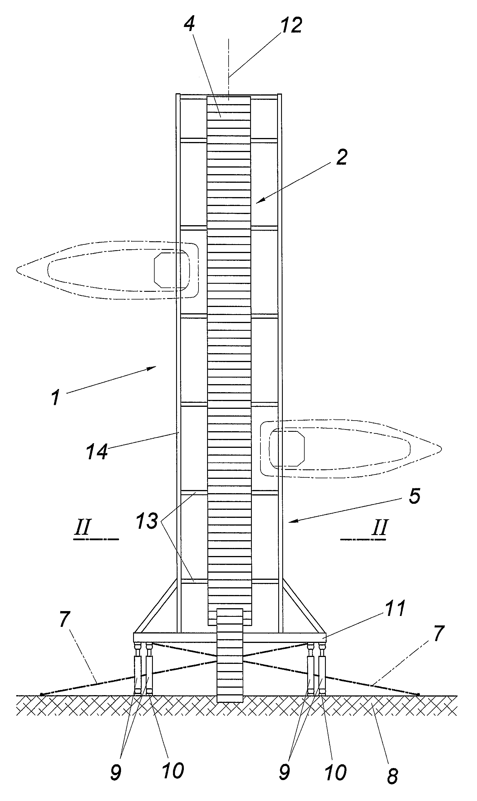
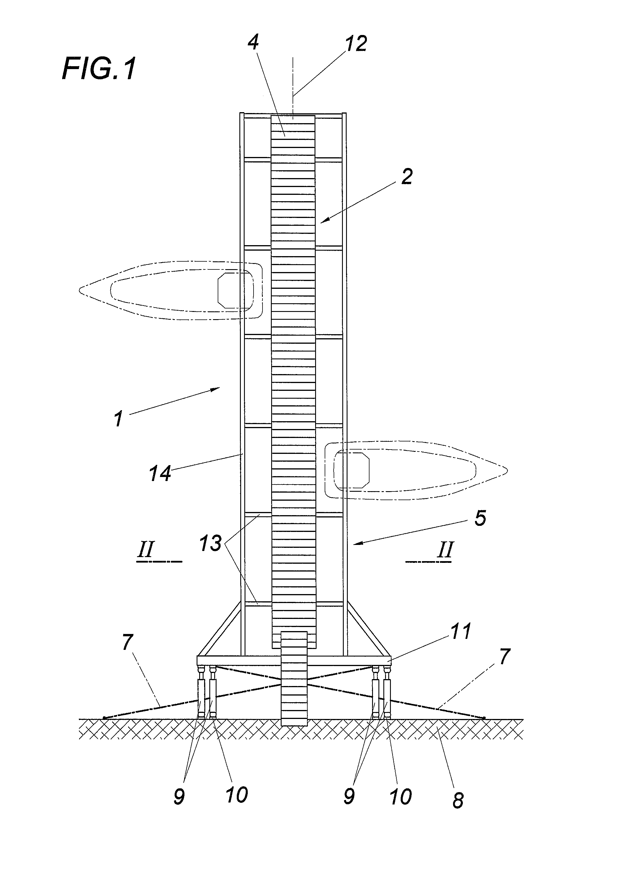
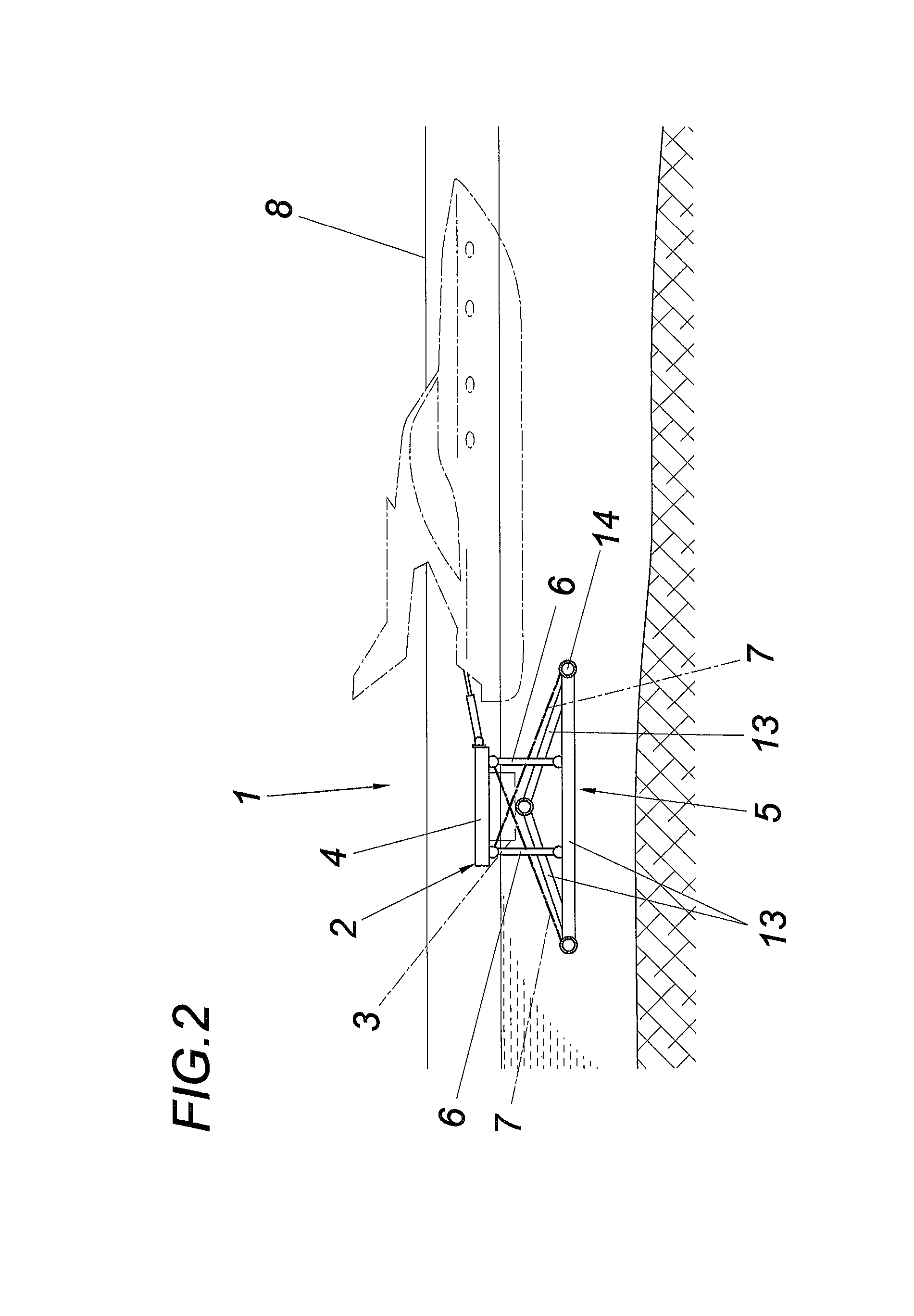
[0022]The device according to the invention for securing floating bodies 1 comprises a floating dock 2 having at least one buoyant element 3, having a path structure 4, and having a framework-like underwater structure 5.

[0023]The path structure 4 has a typical floor covering made of wooden boards or the like and is connected to the framework-like underwater structure 5 of the floating dock 2 via pendulum supports 6 and braced via traction means 7.

[0024]The floating dock 2 is fixed on a landing body 8, a pier, harbor wall, or the like, using at least two holding trees 9, which each engage at one end on the floating dock 2 and at the other end on the landing body 8. The holding trees 9, which are fixed in particular by means of fittings, particularly preferably ball couplings, on the mooring points 10, consist of two subtrees displaceable one inside the other telescopically, which are braced against one another by a spring unit, which absorbs traction and compression forces acting on ...


PUM


Abstract

The invention relates to a device for securing floating bodies (1), in particular platforms and boats, comprising at least one floating dock (2) with at least one buoyancy element (3), a path structure (4), and a framework-like underwater structure (5). In order to provide advantageous disembarkation conditions, the path structure (4) and the framework-like underwater structure (5) of the floating dock (2) are connected to each other via pendulum supports (6) and are braced via pulling means (7), in particular cables and / or claims.

Description

CROSS REFERENCE TO RELATED APPLICATIONS[0001]This application is the National Stage of PCT / AT2014 / 050005 filed on Jan. 9, 2014, which claims priority under 35 U.S.C. §119 of Austrian Application No. A50028 / 2013 filed on Jan. 17, 2013, the disclosures of which are incorporated by reference. The international application under PCT article 21(2) was not published in English.1. FIELD OF THE INVENTION[0002]The invention relates to a device for securing floating bodies, in particular boats, having a floating dock having at least one buoyant element, having a path structure, and having a framework-like underwater structure.2. DESCRIPTION OF THE PRIOR ART[0003]Floating docks are structures which float on the water, and on which, for example, arbitrary floating bodies can in turn be fixed, such as ships, boats, sporting equipment, and the like. Floating docks are used in bodies of water having tidal range as water-level-independent docking points and in harbors, inter alia, also for providin...

Claims


Application Information

Patent Timeline
Patent Type & Authority Patents(United States)
IPC IPC(8): B63C1/02B63B21/00E02B3/06B63B35/34
CPCB63C1/02B63B21/00E02B3/064B63B35/34B63B2021/001B63B35/38E01D15/24Y02A10/11
Inventor FUHRMANN, MICHAEL
Owner DUAL DOCKER
Why Eureka
Try Eureka