Unlock instant, AI-driven research and patent intelligence for your innovation.

Two-input uninterruptible voltage converting device and method thereof

a voltage conversion device and uninterruptible technology, applied in emergency power supply arrangements, process and machine control, instruments, etc., can solve the problems of 1% to 3% energy loss in low-voltage dc circuits during high-voltage operation, energy consumption and resource waste in methods, etc., to achieve more reliable power-off protection, simple circuits, and energy saving

Inactive Publication Date: 2016-12-13
JAGESON ELECTRONICS TECHSHENZHENCO LTD +1
View PDF8 Cites 0 Cited by
  • Summary
  • Abstract
  • Description
  • Claims
  • Application Information

AI Technical Summary

Benefits of technology

[0011]The objective of the invention is to provide a simpler two-input online uninterruptible switch-type voltage converting device and a method thereof, so that the automatic power-off protection can be reliably provided for sensitive equipment and the energy loss of a low-voltage DC (Direct Current) during the normal operation of a high-voltage DC can be avoided.
[0023]allowing the central control unit to sample the voltage at the load end and control the pulse width of the PWM signal outputted by the pulse width modulator after analysis and determination, so that the DC voltage outputted by the load end can be kept stable.
[0024]The two-input uninterruptible voltage converting method converts the high-voltage DC and the low-voltage DC into the two pulse voltages in phase, adaptively selects one pulse voltage with larger pulse amplitude to supply the load with power via the back-end energy storage unit and fly-wheel circuit after the direct intersection, does not need to exactly design the number of turns of the main power transformer to determine an entry point of the low-voltage DC, and can achieve the function of uninterruptible power supply via the online mutual compensation of the high-voltage DC and the low-voltage DC without detecting the state of the high-voltage DC.
[0025]As a high-voltage source and a low-voltage source are connected with each other in series and connected with the back-end energy storage unit and supply the back-end energy storage unit with power uninterruptibly via mutual compensation, the two-input uninterruptible voltage converting device can provide more reliable power-off protection for the sensitive equipment compared with the traditional method for connecting UPSes (Uninterruptible Power Source) in series between the sensitive equipment and a power supply network.
[0026]Moreover, there is no current in the second conversion circuit and no energy loss on the low-voltage DC source during the normal power supply of the high-voltage DC. In addition, the synchronous rectification technology is further adopted. Therefore, the energy can be effectively saved, which meets the current situation of energy saving and emission reduction.
[0027]Furthermore, the device has the advantages of simple circuits, high conversion efficiency, high reliability and low energy consumption, can be widely applied to various kinds of power supply sensitive equipment in the case of AC (Alternating Current) / DC or DC / DC power supply, for example, communication equipment, rail traffic monitoring systems, security systems, IDC (Internet Data Center) equipment, solar energy and AC two-input LED lighting systems and military dual-energy systems.

Problems solved by technology

However, in all the methods, one energy conversion unit must be connected in series on the front of the sensitive equipment, and then the methods also have the defects of energy consumption and resource waste.
However, there is 1% to 3% energy loss in low-voltage DC circuits during the high-voltage operation.

Method used


Image

  • Two-input uninterruptible voltage converting device and method thereof
  • Two-input uninterruptible voltage converting device and method thereof
  • Two-input uninterruptible voltage converting device and method thereof

Examples


embodiment 1

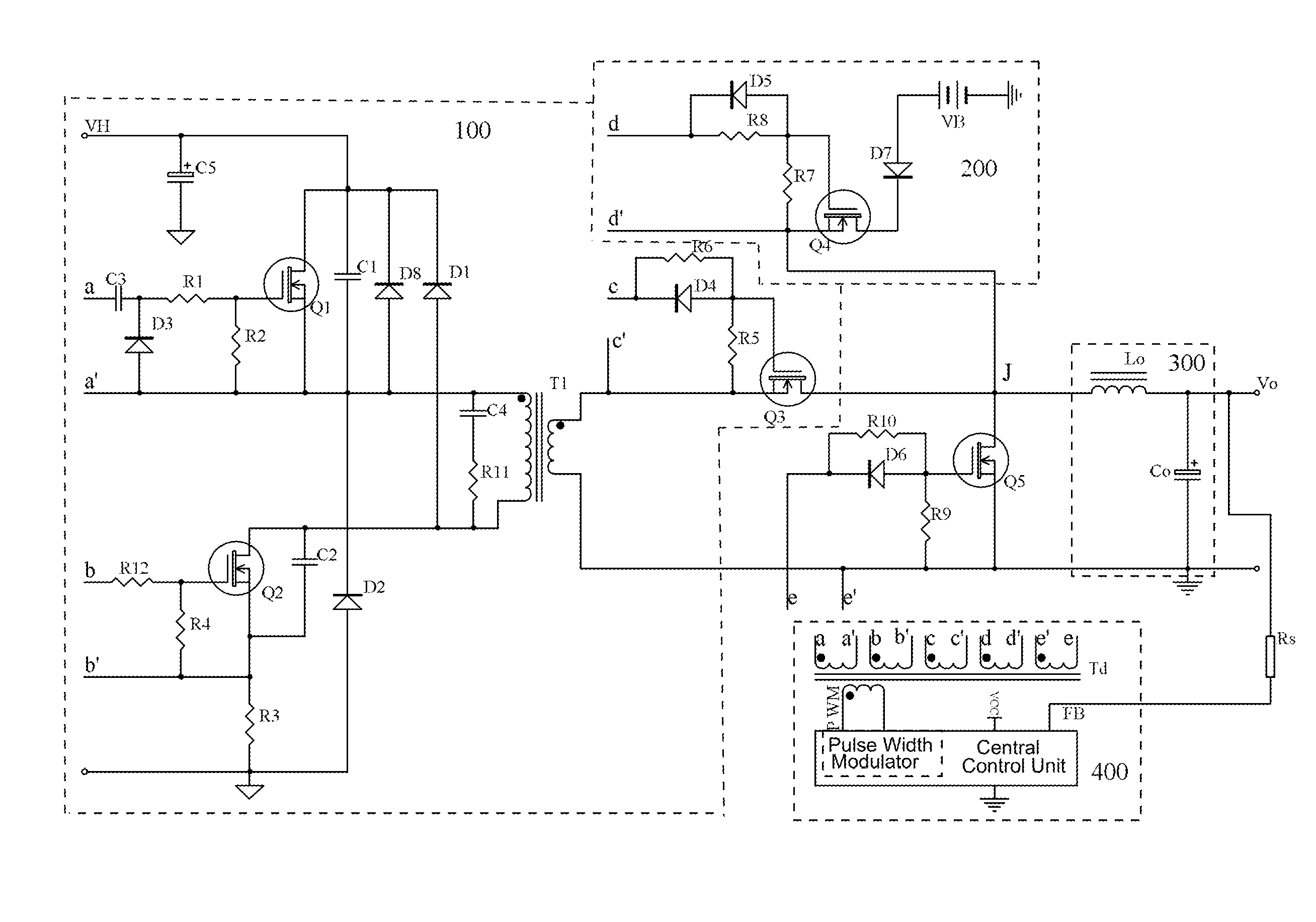
[0033]As illustrated in FIG. 1, the two-input uninterruptible voltage converting device comprises a first conversion circuit 100, a second conversion circuit 200, an energy storage unit 300 and a control unit 400.

[0034]The first conversion circuit 100 has a high-voltage DC (Direct Current) source VH, a main power transformer T1, an upper switch tube Q1 and a lower switch tube Q2 connected to a primary winding of the main power transformer T1, and a switch-type rectifying tube Q3 connected to a secondary winding of the main power transformer T1; and an output end of the switch-type rectifying tube Q3 is taken as an intersection J.

[0035]The second conversion circuit 200 is formed by a low-voltage DC source VB, an isolating diode D7 and a low-voltage switch tube Q4 connected with each other in series in turn; an output end of the second conversion circuit 200 is connected to the intersection J; the minimum allowable voltage of the low-voltage DC source VB is more than the rated output ...

embodiment 2

[0047]As illustrated in FIG. 2, the two-input uninterruptible voltage converting device of the embodiment 2 is basically the same with that of the embodiment 1, with the difference as follows: in the embodiment 1, the switch-type rectifying tube Q3 is driven by the secondary winding cc′ of the pulse transformer Td and synchronously switched on or off with the upper switch tube Q1, the lower switch tube Q2 and the low-voltage switch tube Q4.

[0048]But in the embodiment 2, the switch-type rectifying tube Q3 adopts the bootstrap driving means, namely the switch-type rectifying tube Q3 is driven by a pulse voltage outputted by another secondary winding (namely a bootstrap winding) of the main power transformer T1 and synchronously switched on or off with the upper switch tube Q1, the lower switch tube Q2 and the low-voltage switch tube Q4. In actual application, the amplitude of the pulse voltage generated by the bootstrap winding must be controlled to be within the range specified by a ...

embodiment 3

[0049]As illustrated in FIG. 3, the two-input uninterruptible voltage converting device of the embodiment 3 is basically the same with that of the embodiment 1, with the difference as follows: in the embodiment 1, the switch-type rectifying tube Q3 adopts an MOSFET and is synchronously switched on or off with the upper switch tube Q1 and the lower switch tube Q2, namely adopting the synchronous rectification technology. But in the embodiment 3, the rectifying tube Q3 adopts a Schottky diode (SBD), so that the two-input uninterruptible voltage converting device of the embodiment 3 has the advantages of simpler lines and lower cost. The embodiment 3 is adapted to the case of low power and no need of inverse high-voltage output.


PUM


Abstract

The invention relates to a two-input uninterruptible voltage converting device and a method thereof. The device comprises a first conversion circuit, a second conversion circuit, an energy storage unit, a fly-wheel switch tube and a control unit. The method comprises the following steps of: converting a PWM signal outputted by a pulse width modulator into first, second, third and fourth PWM signals in phase via a pulse transformer; driving the first conversion circuit and the second conversion circuit respectively to operate synchronously; converting a high voltage DC (Direct Current) and a low voltage DC into two pulse voltages in phase to adaptively perform mutual energy compensation via an intersection; and supplying a load with an uninterruptible stable voltage via the back-end energy storage unit and free-wheel circuit. The two-input uninterruptible voltage converting device has the advantages of high circuit conversion efficiency, high reliability and low power consumption.

Description

FIELD OF THE INVENTION[0001]The invention relates to the voltage conversion technology, in particular to a two-input uninterruptible voltage converting device and a method thereof.BACKGROUND OF THE INVENTION[0002]Energy saving is the most important policy for industries in the whole world. With the development of the IT industry, the energy consumed by the application of IT equipment occupies higher and higher proportion in energy consumption. In order to guarantee the reliable and uninterruptible operation of information equipment (such as IDCs (Internet Data Center), banks, insurance, stock markets, wireless communication base stations, repeaters, various EPON devices, security equipment and fire monitoring systems), a plurality of UPSes (Uninterruptible Power Source) are connected between sensitive equipment and a power supply network in series. In a series system formed by the power supply network, the UPSes and the sensitive equipment (load), the UPSes must be subjected to main...

Claims


Application Information

Patent Timeline
Patent Type & Authority Patents(United States)
IPC IPC(8): H02J1/00H02J9/06H02M1/10H02M3/335
CPCH02J9/061H02J9/062H02M1/10H02M3/33592Y02B70/1475Y10T307/675Y02B70/10Y02B70/30Y04S20/20
Inventor YIM, FRANK MAU SHIN
Owner JAGESON ELECTRONICS TECHSHENZHENCO LTD