Device and method for measuring physical parameters using saw sensors

a sensor and physical parameter technology, applied in the field of sensors, can solve the problems of insufficient temperature sensitivity of high-temperature saw crystal orientation, insufficient prior art of sensing devices for measuring parameters such as pressure, torque, strain, etc., and achieve the effect of reliably providing sensing measurements

Inactive Publication Date: 2015-01-15
ENVIRONETIX TECH
View PDF0 Cites 37 Cited by
  • Summary
  • Abstract
  • Description
  • Claims
  • Application Information

AI Technical Summary

Benefits of technology

[0019]6. The ability for signal processing to support accurate extraction of desired measurand from spectral data in real time.
[0020]The disclosed technology includes a sensor which can be passive and wireless, and that provides information for calculating temperature, strain, and other measurands in an accurate manner. A particularly unique feature of the disclosed technology is its ability to provide sensing measurements reliably in a variety of harsh and hostile environments. The disclosed technology provides in situ measurements of parameters of extreme interest to original equipment manufacturers in a variety of industries, including aerospace, power generation and oil production. Additionally, the disclosed technology advances efforts to produce commercial health monitoring systems for entities (such as power plants) and components.

Problems solved by technology

Conventional SAW piezoelectric substrates cannot withstand rapid thermal shock or prolonged exposure to temperatures above 600° C. due to crystal phase transitions, thermal shock cracking, or accelerated crystal decomposition and degradation.
Furthermore, currently identified orientations for high temperature SAW crystals suffer from insufficient temperature sensitivity over large temperature ranges, e.g. 0° C.-1,000° C., needed for reliable temperature sensing in harsh environments.
Newer piezoelectric crystals from the Langasite family of crystals (LGX), including Langasite (LGS) and Langatate (LGT), can be operated near their melting points (˜1470° C. for LGS), but prior art or commercially available substrates are cut to crystallographic orientations with useful propagation directions that are temperature compensated around room temperature and typically display insufficient temperature sensitivity below 150° C. However, the use of alternative substrate cuts and propagation directions with these materials can allow increased temperature sensitivity due to the anisotropic nature of the crystalline substrates employed, and at the same time still display attractive features such as moderate to high piezoelectric coupling, low power flow angle, and low diffraction to achieve a greater sensor operational temperature range (<0° C.-1,000° C.).
The use in prior art of SAW sensing devices for measuring parameters such as pressure, torque, strain and others also has not fully solved the problem of accurate extraction of parameters of interest from a SAW device as a function of the measurands.
For these cases such conditions lead to the problem of under-sampling the state of the sensor, which upon subsequent spectral analysis of the sensor state over time results in non-unique determination of dynamic measurand frequencies as a result of aliasing effects.
The obvious solution is to sample faster, but for many applications this solutions becomes too expensive and increases complexity of the electronics and its configuration, as the amount of parallel running hardware required and the speed at which it operates increases.
In many cases the required high operating temperatures (above 300° C.) and the presence of corrosive media may impose drastic limitations on the sensor materials.
For instance, commercially available silicon piezoresistive pressure sensors are often unable to work at such high temperatures and reliably measuring in situ parameters of interest on rotating parts in harsh environments, e.g. turbine blades in or near the hot section of a jet engine or gas turbine, poses additional challenges.

Method used


Image

  • Device and method for measuring physical parameters using saw sensors
  • Device and method for measuring physical parameters using saw sensors
  • Device and method for measuring physical parameters using saw sensors

Examples


Embodiment Construction

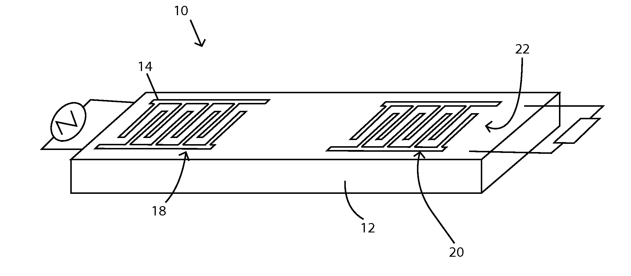
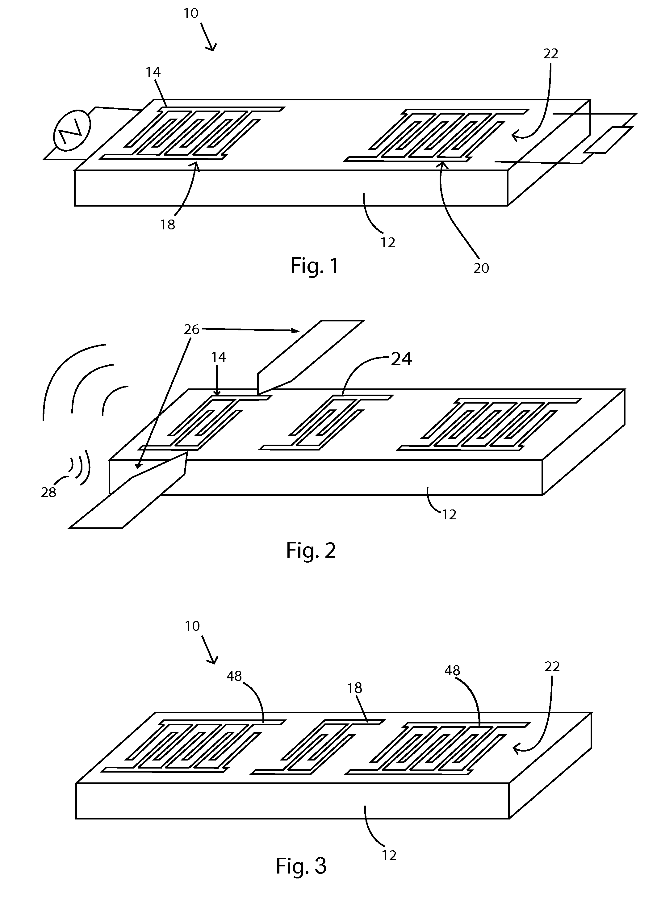
[0034]As shown in FIG. 1, the device 10 includes a piezoelectric crystal 12 on which is affixed a layer of metallic electrodes 22. The input 18 and output 20 structure each consists of a periodic interdigitated transducer (IDT) 14 electrode structure of several wavelength periodicities, λ, in width. The synchronous operation of the IDT at the surface launches an electromechanical surface acoustic wave (SAW) which propagates at ˜3×10³ m / s, or approximately five orders of magnitude slower than the propagation of the electromagnetic wave (EM) in vacuum (3×10⁸ m / s). This allows significant delay from input to output, namely five orders of magnitude longer delay than for an EM wave propagating in air using a similar sized structure. For this reason, the device using the IDT geometry shown in FIG. 1 is called a delay line, and represents one of many possible signal processing devices enabled by SAW technology. These devices are very small, ranging from a few millimeters to sub-millimeters...


PUM


Abstract

A SAW mode sensor for sensing parameters such as temperature, pressure, and strain. The sensor is made of a piezoelectric crystal cut at selected angles, with an attached electrode layer with a signal receiver and signal transmitter. The signal receiver initiates a wave in the substrate which propagates in the substrate and the speed of the wave and amplitude of the wave is interpreted as the parameter being sensed.

Description

TECHNICAL FIELD[0001]The disclosed technology generally relates to sensors, and more particularly to surface acoustic wave sensors for harsh environments.BACKGROUND[0002]Microwave acoustic sensors rely on acoustic wave technology where acoustic wave modes are excited and detected in an environmentally sensitive substrate using integrated electromechanical transducer(s). Among the acoustic wave modes that can be used for sensing—e.g. bulk acoustic wave (BAW), film bulk acoustic resonators (FBAR), acoustic plate modes (APM), and surface acoustic waves (SAW)—the SAW offers the greatest flexibility for direct implementation of distinct filtering and sensing applications as the fabrication process is comparatively simple (typically only one metallic layer patterning process is required), the devices exhibit low propagation loss (wave is guided by the surface) permitting long signal delays in a relative small area, and the ability to manipulate the mode propagation path in a complex manne...

Claims


Application Information

Patent Timeline
Patent Type & Authority Applications(United States)
IPC IPC(8): H01L41/113G01H11/08
CPCH01L41/1132G01H11/08G01N29/2462G01K11/265G01L1/165H03H9/0259H03H9/02598G01N2291/0423G10K11/36H03H9/02543H10N30/302
Inventor POLLARD, THOMASMCCANN, DONALD
Owner ENVIRONETIX TECH
Why Eureka
Try Eureka