Vacuum insulation panel with improved rupturing and preparation method thereof

a vacuum insulation panel and rupturing technology, which is applied in heat-proofing, mechanical equipment, synthetic resin layered products, etc., can solve the problems of patents that do not disclose improvements in the the difficulty of handling the vacuum insulation panel, so as to improve the rupturing resistance. , increase the thermal welding ratio of the thermal welding portion, the effect of easy processing into various shapes

Active Publication Date: 2016-12-20
ES GLOBAL CO LTD
View PDF14 Cites 5 Cited by
  • Summary
  • Abstract
  • Description
  • Claims
  • Application Information

AI Technical Summary

Benefits of technology

[0020]The vacuum insulation panel exhibits improved rupturing resistance at an edge and the like by increasing a thermal welding ratio of a thermal welding portion of a shell, and can be easily processed into various shapes.
[0021]In addition, even though a through-hole is formed in the shell excluding the core of the vacuum insulation panel, the vacuum insulation panel can maintain stability and excellent heat insulation properties.

Problems solved by technology

However, since an unwelded portion such as an edge of the shell is vulnerable to physical impact and thus is likely to rupture, there is difficulty handling of the vacuum insulation panel.
However, this patent does not disclose improvement in a welding ratio of the thermal welding portion by welding an unwelded portion of the shell, such as an edge of the shell, and the like.

Method used


Image

  • Vacuum insulation panel with improved rupturing and preparation method thereof
  • Vacuum insulation panel with improved rupturing and preparation method thereof
  • Vacuum insulation panel with improved rupturing and preparation method thereof

Examples


example 2

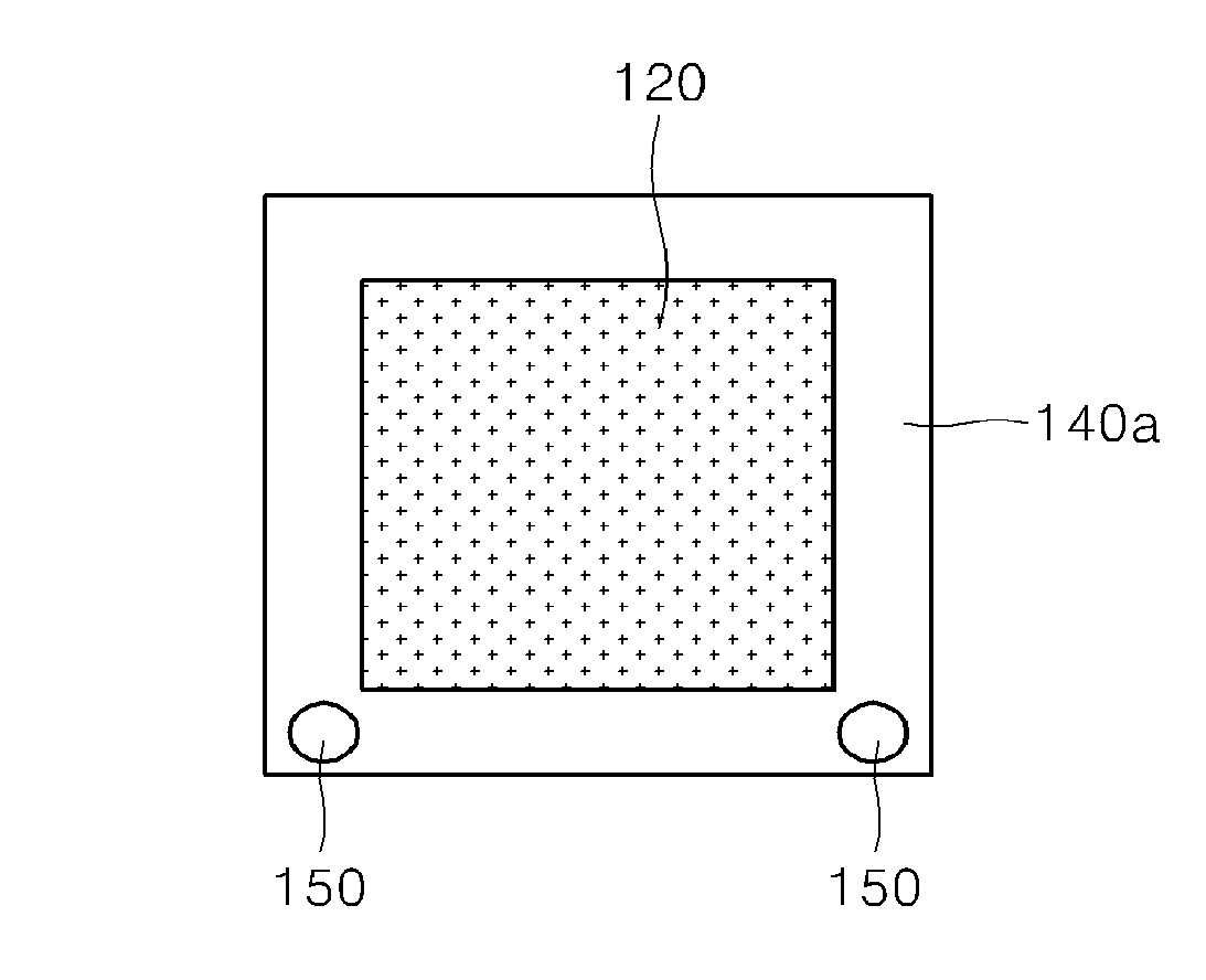
[0070]A quadrangular through-hole having a size of 40 mm×50 mm (width×length) was formed in a lower end portion of a core, followed by placing the core in a shell, thereby manufacturing a vacuum insulation panel. Here, the shell and a getter were the same as the shell and the getter of Example 1, respectively, and heat treatment was also performed in the same manner as in Example 1. After heat treatment, the shell inside the through-hole was cut to a size of 30 mm×40 mm (width×length), followed by measurement of thermal conductivity. As a result, the vacuum insulation panel had a thermal conductivity of 2.57 mW / mK.

experimental example

Sealing Strength of Vacuum Insulation Panel

[0078]Sealing strength of each of the vacuum insulation panels prepared in Example 1 and Comparative Example 2 was measured. As shown in FIG. 5, a sample of the thermal welding portion was cut to a width of 15 mm, a length of 10 mm and a total length of 50 mm at each of No. 1 to No. 10 positions. The sample was mounted on a tensile tester (Universal Testing Machine (5TON), Shimadzu Co., Ltd.) such that a sealing portion could be subjected to 180° peeling in a vertical direction, followed by measuring strength when the sealing portion was peeled off under a load cell of 50 kgf. Average values of sealing strength were calculated and shown in Table 2.

[0079]

TABLE 2Measured result of Measured result of sealing strength ofsealing strength ofspecimen of specimen of Comparative Example 1 (kgf)Example 2 (kgf)No. 112.85.0No. 211.74.2No. 310.75.0No. 411.85.3No. 510.85.3No. 614.24.8No. 712.04.7No. 813.05.4No. 912.04.6No. 1011.94.1Average12.14.84

[0080]R...


PUM

PropertyMeasurementUnit
thicknessaaaaaaaaaa
thicknessaaaaaaaaaa
temperatureaaaaaaaaaa

Abstract

Provided is a vacuum insulation panel comprising: a core material; and a shell material for covering the core material, wherein the shell has a layered structure comprising a surface protective layer, a metal barrier layer, and a thermal deposition layer from the outside, and the sealing strength of the vacuum insulation panel is 5-15 kgf. In addition, provided is a method for preparing the vacuum insulation panel, comprising the steps of: preparing the shell material by sequentially layering the thermal deposition layer, the metal barrier layer and the surface protective layer; inserting the core material between the shell material; reducing pressure and sealing the shell material so as to form a vacuum insulation panel; and heat treating the vacuum insulation panel, wherein the sealing strength of the vacuum insulation panel is 5-15 kgf.

Description

TECHNICAL FIELD[0001]The present invention relates to a vacuum insulation panel having improved rupturing resistance, and a method for manufacturing a vacuum insulation panel, which includes heat treatment to minimize an unwelded portion of a shell.BACKGROUND ART[0002]In currently commercially available vacuum insulation panels, inorganic compounds, such as glass wool, fumed silica, aerogel and the like, are used as a core. In addition, nylon / PET / aluminum foil, or an aluminum deposition layer and a welding layer such as PE, PP and the like are used for a shell. Further, to secure long term performance, vacuum insulation panels include a getter such as quicklime (CaO), zeolite and the like, a moisture absorbent such as silica gel and the like, and metal powder.[0003]However, since maintenance of an internal vacuum level is the most important factor in performance of the vacuum insulation panels, the internal vacuum level is maintained by sealing the shell at a high vacuum of 10 Pa or...

Claims


Application Information

Patent Timeline
Patent Type & Authority Patents(United States)
IPC IPC(8): F16L59/065B32B37/30F16L59/08B32B7/12B32B15/085B32B27/20B32B3/04B32B37/06B32B38/04B32B37/10E04B1/80
CPCF16L59/065B32B3/04B32B7/12B32B15/085B32B27/205B32B37/06B32B37/10B32B37/30B32B38/04F16L59/08B32B2038/047B32B2307/304B32B2307/7244B32B2323/04B32B2323/10E04B1/803Y10T156/1056Y10T428/231F16L59/04
Inventor MIN, BYUNG-HOONHWANG, SUNG-SEOCKJEON, SEUNG-MINHAN, JUNG-PIL
Owner ES GLOBAL CO LTD
Why Eureka
Try Eureka