Spatially selective detection using a dynamic mask in an image plane

a dynamic mask and image plane technology, applied in the field of three-dimensional laser scanners, can solve the problems of sluggish performance, noisy and expensive instruments, and voluminous objects, and achieve the effect of less critical design, less voluminous objects, and less voluminous objects

Active Publication Date: 2016-12-27
IEE INT ELECTRONICS & ENG SA
View PDF12 Cites 7 Cited by
  • Summary
  • Abstract
  • Description
  • Claims
  • Application Information

AI Technical Summary

Benefits of technology

[0009]A lens or a more complex optical system images the scene which is scanned by the illumination laser beam. In the image plane of this lens or optical system a device selects a region of interest (ROI) of variable shape and size which is continuously repositioned and adapted such that mainly the image of the illuminated spot is captured within the ROI. The shape and size of the ROI can be adapted continuously as the illumination beam scans over the scene. The device realizing the selection of the ROI separates all light paths lying inside the ROI from those lying outside the ROI, such that the light from inside the ROI can be detected separately.
[0033]It should be noted that in case the light path for detection coincides partially with that of the illumination light path, i.e. traverses a certain amount of optical elements in reverse of the illumination, a certain degree of spatial selectivity in the detection is already achieved. However, the optics for imaging the illuminated point on to the single detector in this case would have to achieve a high quality, near to diffraction limit imaging in order to reach the signal selectivity which this invention aims at. The invention proposes a solution which requires less a critical design of the optical system and can accordingly be less expensive. Furthermore the invention gives a larger design freedom for the detection system, enabling optimization of the light gathering ability independent of optical requirements related to the technical realization for the scanning of the laser beam. The additional flexibility in the way of separating signal light from background light enables useful enhancements of functionality.

Problems solved by technology

This leads to rather voluminous, often noisy and expensive instruments.
Since size and weight of the optical elements increases accordingly, this can result in even more cumbersome constructions and sluggish performance when the laser beam is scanned by mechanical actuation of optical elements.

Method used


Image

  • Spatially selective detection using a dynamic mask in an image plane
  • Spatially selective detection using a dynamic mask in an image plane
  • Spatially selective detection using a dynamic mask in an image plane

Examples


Embodiment Construction

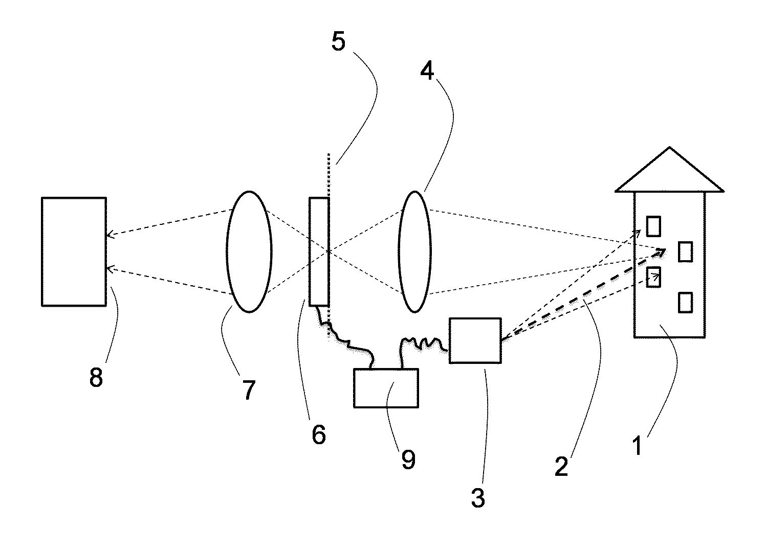
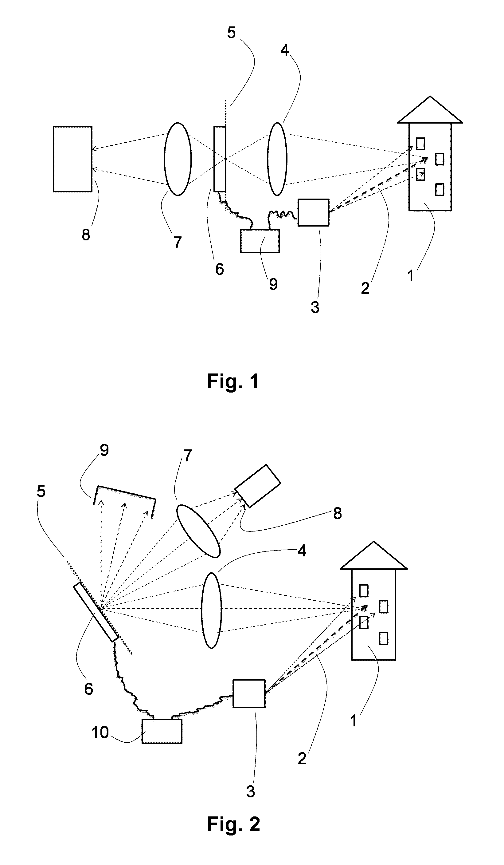
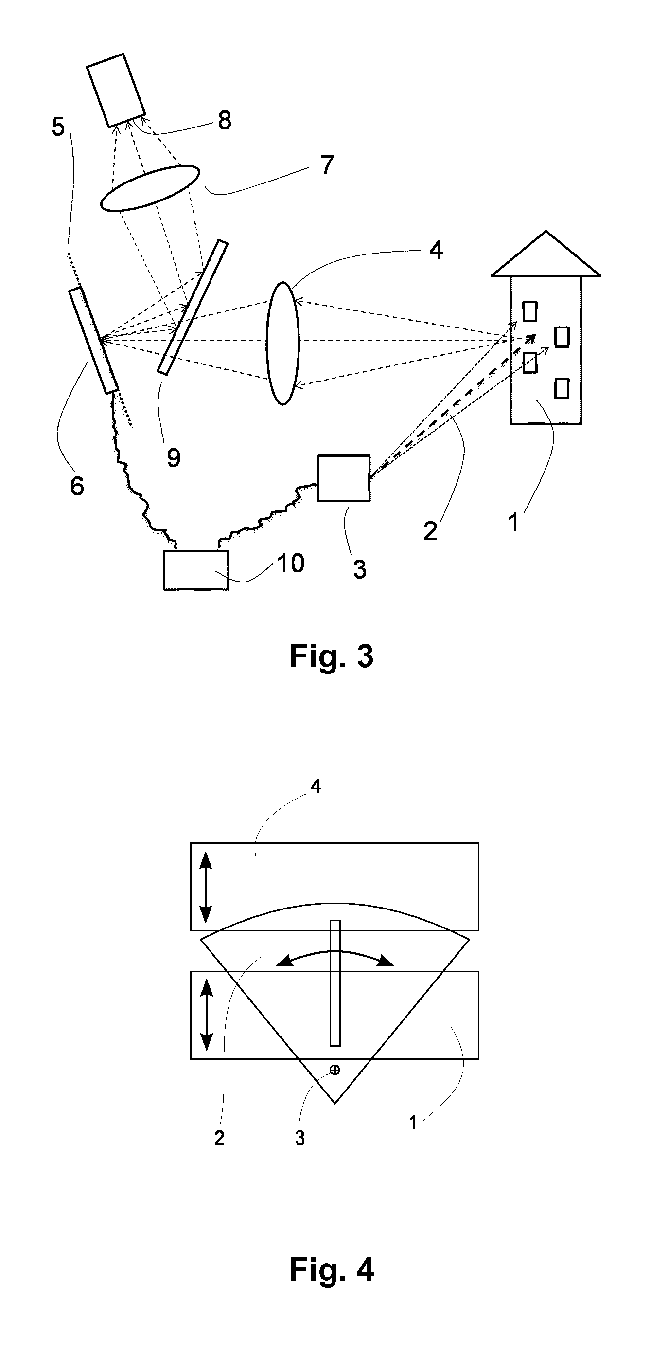
[0042]The main aspect of the present invention concerns an additional component of the light detection system of a three-dimensional laser scanner providing performance and functionality enhancements. It mainly serves to improve the signal-to-noise ratio in detection and to block disturbing background and stray light from detection, the problem described under a) above. The invention also relates to some aspects of the design of the light detection system and of the scanner as a whole in order to accommodate the new component in the system and to obtain the enhanced performance and functionality. Further aspects of the invention relate to solutions to the problems of interference of similar scanner instruments working on the same scene described above under point b), and to solutions to problems of the scanner operation in bad atmospheric conditions addressed above under point c). The solutions proposed in the last two problem categories are for one part enabled by the device introd...


PUM


Abstract

A three-dimensional laser scanner instrument for acquiring three-dimensional geometric data of a scene (1) comprises an illumination system (3) for generating a light beam (2) and for scanning an illumination point of said light beam (2) through said scene (1), a light detection system (6-9) comprising at least one light detector (8), said light detection system being arranged to receive light from said scene (1), and an optical system (4) for imaging light scattered in or reflected from said scene (1) onto said light detection system (6-9). The light detection system (6-9) further comprises a controllable filter element (6) for dynamically discriminating light impinging from selected regions of said scene (1) and a control unit (9) operatively connected to said controllable filter element (6) and to said illumination system (3), wherein in operation of said scanner instrument, said filter element (6) is controlled by said control unit (9) so as to guide only light impinging from a selected, spatially delimited region around said illumination point in said scene (1) onto said at least one light detector (8).

Description

TECHNICAL FIELD[0001]The present invention generally relates to the area of three-dimensional laser scanners, i.e. instruments which acquire three-dimensional geometric data of a scene of objects by sequentially pointing a pulsed or modulated laser beam at different points in the scene and detecting the light backscattered from a scene object with a resolution in time allowing to determine the distance to the scene object by the time-of-flight method. The invention more particularly applies to LADAR, LIDAR, laser ranging and / or three-dimensional laser scanners.BACKGROUND ART[0002]Many different designs of three-dimensional laser scanner instruments exist. Some of these instruments reach a very high precision, but can require precise alignment and long measurement times. Many possible applications for such instruments are conceivable in consumer products, when both costs and the degree of complication of their operation can be reduced.[0003]Although concepts exist for LIDAR imagers w...

Claims


Application Information

Patent Timeline
Patent Type & Authority Patents(United States)
IPC IPC(8): G01B11/24G01S7/481G01S17/89G01S17/42G01S17/00G01B11/02G01S7/487G01C15/00G02B26/02G02B26/08
CPCG01B11/02G01C15/002G01S7/487G01S7/4816G01S7/4817G01S17/003G01S17/42G01S17/89G02B26/023G02B26/0833
Inventor HERSCHBACH, NORBERT
Owner IEE INT ELECTRONICS & ENG SA
Why Eureka
Try Eureka