

Dual sensor head configuration in a fluid flow or liquid level switch
a technology of fluid flow or liquid level switch and dual sensor head, which is applied in the direction of liquid/fluent solid measurement, level indicators by physical variable measurement, instruments, etc., can solve the problems of inability to accept dual installations, inability to achieve dual installation, and inability to tolerate false positives. , to achieve the effect of increasing the reliability of such a sensor, low weight, size and power consumption
- Summary
- Abstract
- Description
- Claims
- Application Information
AI Technical Summary
Benefits of technology
Problems solved by technology
Method used
Image

Examples
Embodiment Construction
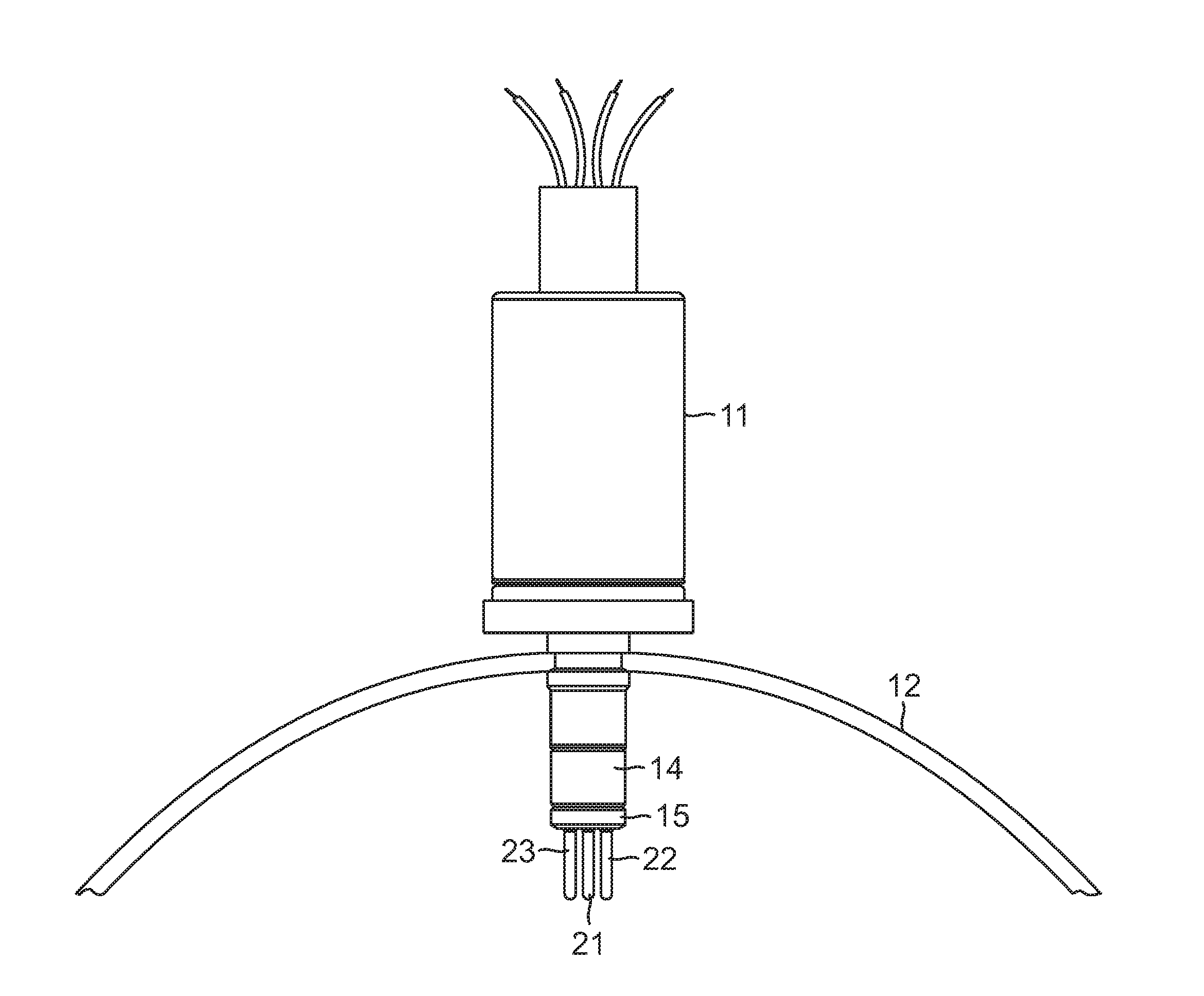
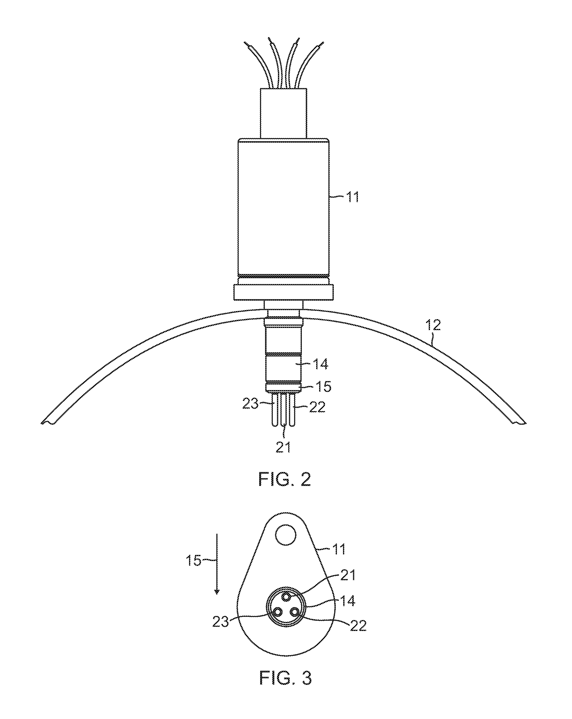
[0008]It is a purpose of this apparatus to achieve a very high level of reliability while maintaining low weight, size, and power consumption in sensing fluid flow or liquid level of a medium or process fluid. The switch design disclosed herein greatly increases the reliability of such a sensor by providing fully redundant and separated output signals which are matched or compared, the sensor arrangement being in the same outline dimension envelope as previously provided in single sensor designs. This is accomplished while maintaining a single installation location on the system. The device assures continued operation in spite of a failure to one of the two redundant channels, thereby reducing the probability of an erroneous low flow or dry signal caused by a single sensor failure. A possible consequence of an erroneous low flow or dry signal includes shutting down a very complex processing plant at an extremely high cost. It is important that there not be false indications of those...
PUM
 Abstract
Description
Claims
Application Information