
Compensating for loss of current through shorted tunneling magnetoresistance sensors

a technology of shorted tunneling magnetoresistance and compensating current loss, which is applied in the field of data storage systems, can solve problems such as dielectric breakdown, current bypassing, and damage to tjs

Inactive Publication Date: 2016-12-27
IBM CORP
View PDF7 Cites 7 Cited by
  • Summary
  • Abstract
  • Description
  • Claims
  • Application Information

AI Technical Summary

Benefits of technology

The present invention provides methods, systems, and computer programming for compensating for loss of current through shorted tunneling magnetoresistance (TMR) sensors in a magnetic head. The invention uses probability algorithms to determine which TMR read sensors are allowed to function at certain voltage limits. By doing so, the invention prevents dielectric breakdown and ensures the continued functioning of the drive. In summary, the technical effect of the invention is to improve the reliability and performance of magnetic heads and to prevent damage to the data being recorded.

Problems solved by technology

Electrical shorts across these thin TJs can result in current bypassing the bulk area of the TJ and going through the short.
Shorts can occur from various sources, such as dielectric breakdown or by scratches which occur during manufacturing (lapping) or in a tape drive by asperities on the tape which can cause scratches.
TJs can be damaged by dielectric breakdown, and the mean dielectric breakdown time for a group of self-similar TMRs subjected to a voltage stress decreases with increasing voltage.
The process of running tape across a TMR sensor can also result in a short across the TJ.
In this case, often the short diverts current away from the active portion of the TMR, and at a fixed current, results in a drop in amplitude.

Method used


Image

  • Compensating for loss of current through shorted tunneling magnetoresistance sensors
  • Compensating for loss of current through shorted tunneling magnetoresistance sensors
  • Compensating for loss of current through shorted tunneling magnetoresistance sensors

Examples


Embodiment Construction

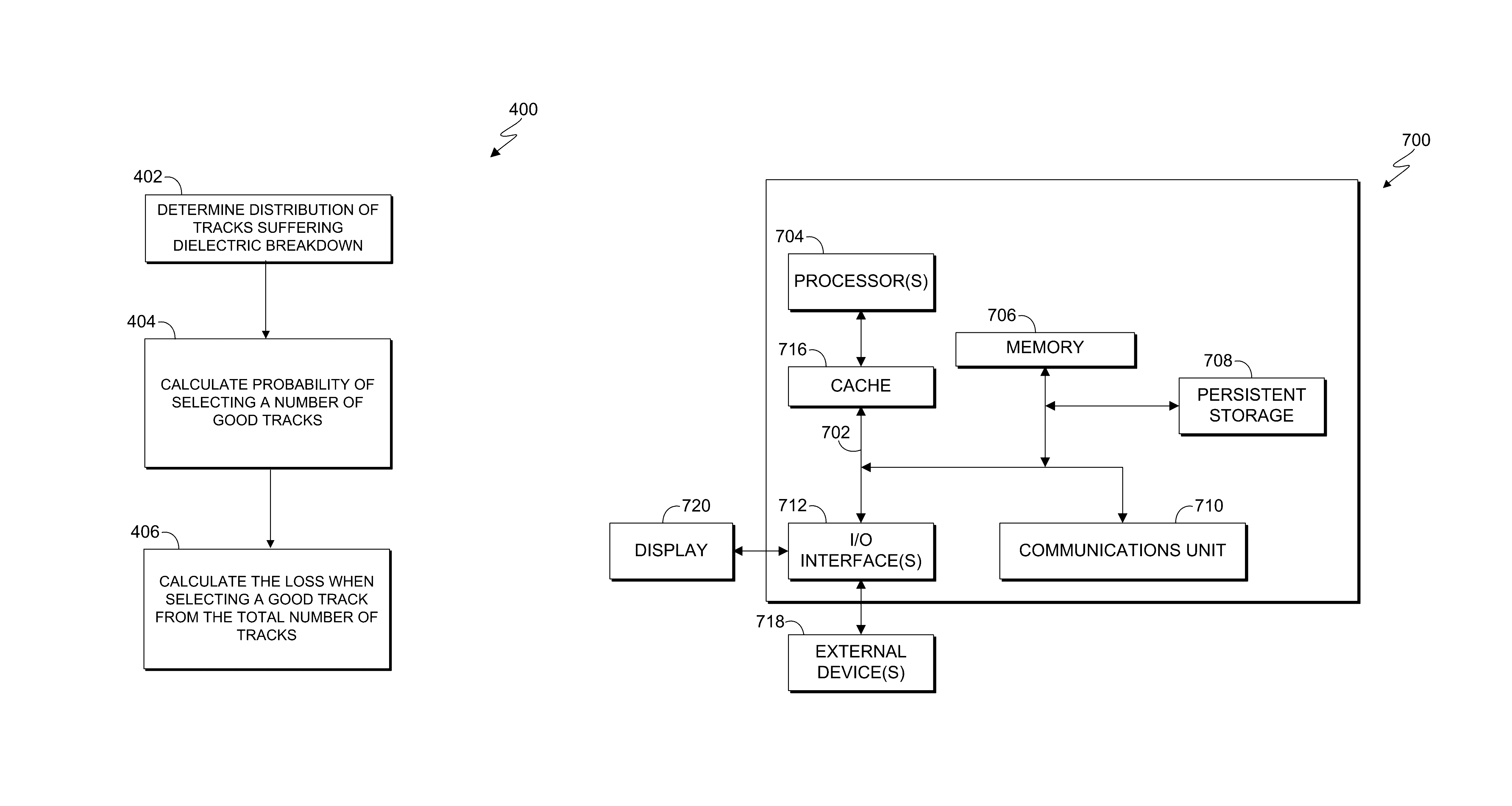
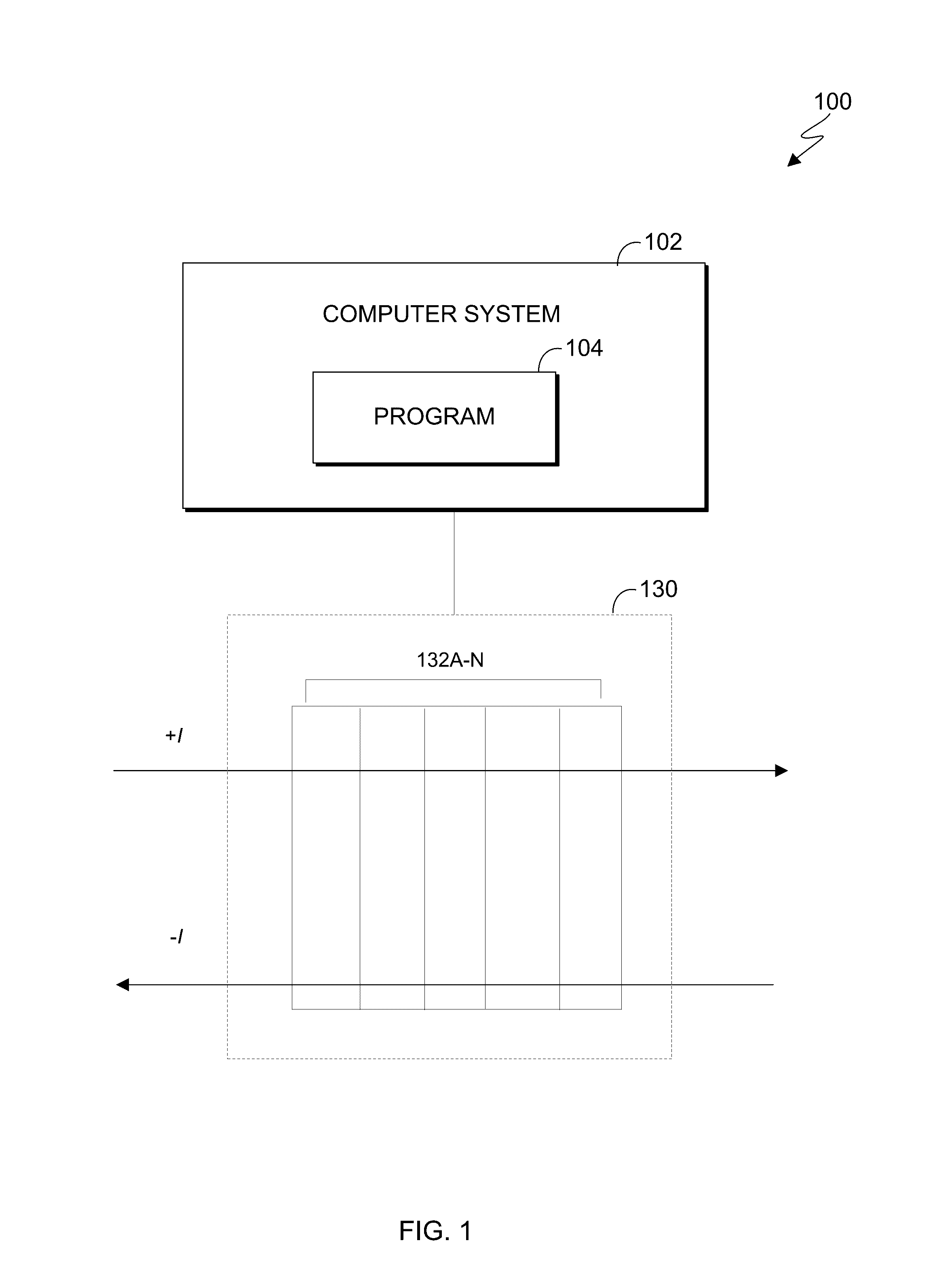
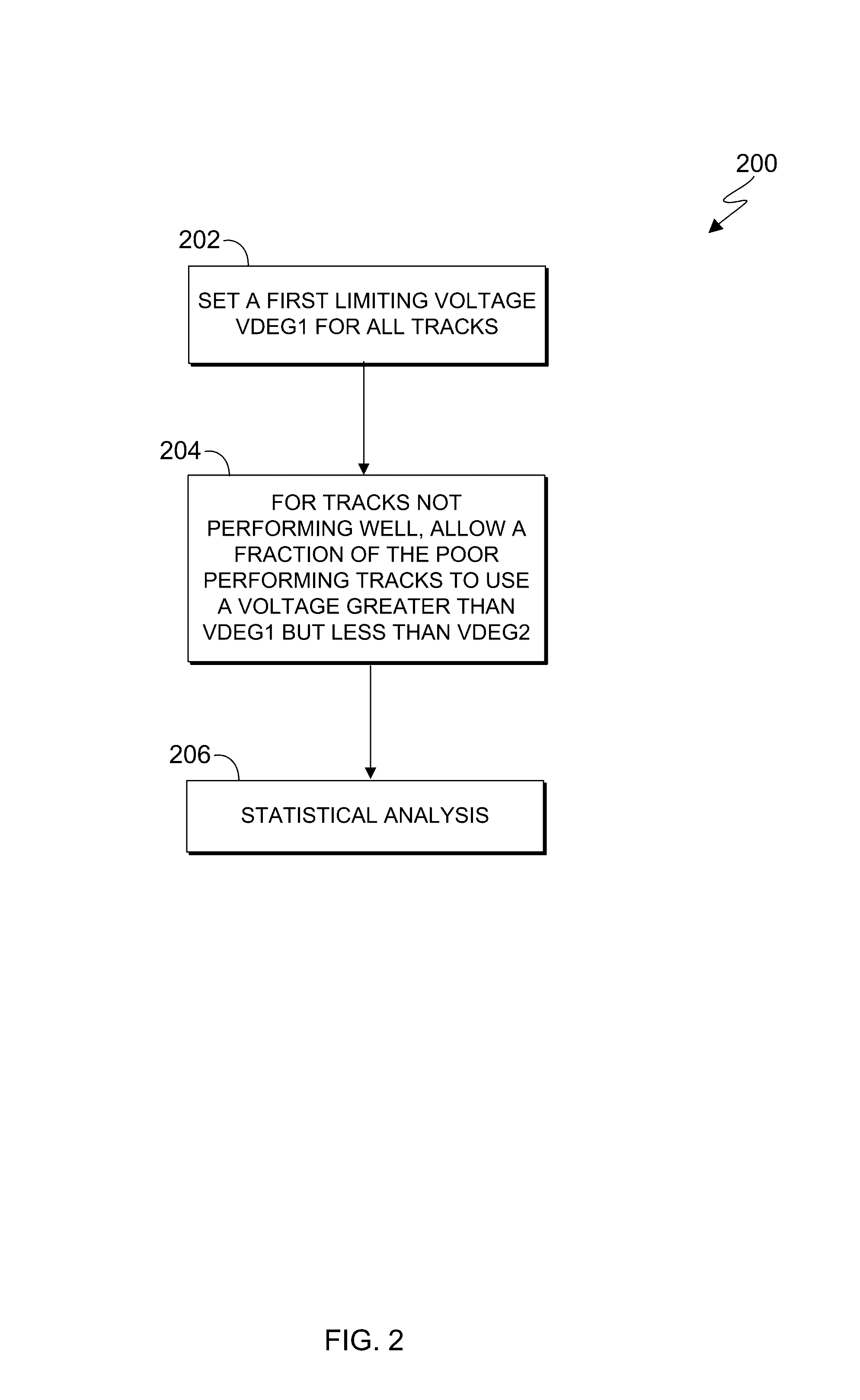
[0016]Embodiments of the present invention provide reliable systems and methods for compensating for the loss of current through a defective magnetic recording TMR sensor due to electrical shorting across the TMR. In one embodiment, a bias current is chosen for a magnetic head with multiple read sensors, in order to statistically avoid dielectric breakdown, by setting an upper limit voltage for the majority of read elements. If there is one or more read elements which functions poorly, the drive selects another bias current which is above the upper limit voltage, but below a higher second voltage limit. Furthermore, embodiments of the present invention can be used to respond to TMR read elements which have undergone shorting events, by setting the bias current and either sequestering a section of the tape where the short has occurred or slowing the velocity of the tape when the head passes over a section of the tape where the short has occurred, enabling the defective sensor to achi...


PUM

PropertyMeasurementUnit
thicknessaaaaaaaaaa
voltageaaaaaaaaaa
dielectric breakdownaaaaaaaaaa

Abstract

Embodiments of the present invention provide methods, systems, and computer program products for compensating for loss of current through shorted tunneling magnetoresistance (TMR) sensors. In one embodiment, for a magnetic head having multiple TMR read sensors, a first voltage limit is set for most parts and a second voltage limit is set for all of the parts. A number of TMR read sensors which are allowed to function between the first and the second voltage limits is determined using a probability algorithm, which determines the probability that the application of the second voltage limit will result in a dielectric breakdown within an expected lifetime of a drive is below a threshold value. For the number of TMR read sensors which are allowed to function at voltages between the first and second voltage limits, a determined subset of those sensors are then allowed to function at the second voltage limit.

Description

BACKGROUND OF THE INVENTION[0001]The present invention relates generally to the field of data storage systems, and more particularly to compensating for the loss of current through shorted tunneling magnetoresistance (TMR) sensors.[0002]TMR sensors can be used to read magnetic data from a magnetic tape media. The thickness of the tunnel junction (TJ) is very small, of the order of 1 nm. Electrical shorts across these thin TJs can result in current bypassing the bulk area of the TJ and going through the short. Shorts can occur from various sources, such as dielectric breakdown or by scratches which occur during manufacturing (lapping) or in a tape drive by asperities on the tape which can cause scratches.[0003]TJs can be damaged by dielectric breakdown, and the mean dielectric breakdown time for a group of self-similar TMRs subjected to a voltage stress decreases with increasing voltage. The process of running tape across a TMR sensor can also result in a short across the TJ. In this...

Claims


Application Information

Patent Timeline
Patent Type & Authority Patents(United States)
IPC IPC(8): G11B5/39G11B20/18
CPCG11B5/39G11B20/1816G11B5/00813G11B5/3977G11B5/40G11B5/3903G11B5/4984G11B20/18G11B5/02G11B5/3948G11B2020/1826
Inventor AHMAD, SAID A.CZARNECKI, WLODZIMIERZ S.GALE, ERNEST S.IBEN, ICKO E. T.
Owner IBM CORP
Learn More