Functional implant

a functional and implant technology, applied in the field of functional implants, can solve the problems of delaying the surgery time, additional teeth damage, and the tooth root is not easily removed from the artificial tooth root, so as to prevent additional teeth damage, reduce the amount of shock applied, and facilitate separability

Inactive Publication Date: 2017-01-03
HIGH DENTAL KOREA
View PDF12 Cites 0 Cited by
  • Summary
  • Abstract
  • Description
  • Claims
  • Application Information

AI Technical Summary

Benefits of technology

[0021]According to the present invention, the functional implant has the crown having the abutment insertion recess formed inside the crown body and the coupling guide portion formed on the inner peripheral wall of the abutment insertion recess through the sequential application of the scratch surface, the silica layer, the zirconia primer layer, and the resin to the inner peripheral wall of the abutment insertion recess, so that the crown is detachably coupled to the abutment by means of press-fitting, not by means of screw-fastening or cementing, thus allowing the crown to be easily separated from the abutment for the repair and correction.
[0022]Further, the functional implant according to the present invention has the crown easily separable from the abutment, thus reducing the shocks applied to adjacent teeth, when separated, to prevent additional teeth damages.
[0023]Furthermore, the functional implant according to the present invention has the crown made through milling, not through casting, thus reducing errors to ensure good fitness and passivity.
[0024]Additionally, the functional implant according to the present invention has the crown having good fitness and passivity, thus preventing the crown from being separated from the abutment after surgery to extend the life span of the crown.

Problems solved by technology

The connection post for supporting the artificial tooth has an inclined surface formed on the portion accommodated into the artificial tooth root in such a manner as to be tightly engaged and fastened with the artificial tooth root by means of the screw, and accordingly, even if the screw is separated from the artificial tooth root so as to exchange the artificial tooth, the inclined surface of the connection post tightly engaged with the artificial tooth root is not easily removed from the artificial tooth root, thus delaying the surgery time due to the consumption of lots of time for the separation of the connection post.
If the connection post is not easily separated from the artificial tooth root, it should pull out by means of a tool like pliers, but in this case, shocks may be applied to adjacent teeth, thus causing additional teeth damages.
So as to allow the connection post to be fastened to the artificial tooth root, further, the screw should be inserted into the connection post to perform the fastening, which makes it very inconvenient in performing the implant surgery and causing the escape or loss of the screw at the time when the connection post is separated.
In case where the impression is made in a patient's oral cavity, however, it is hard to make a real impression.
Accordingly, errors may be generated in making the impression, which will sequentially occur in the model making, pin-work, wax-up, investment, casting and polishing, thus failing to ensure the fitness and passivity of the artificial tooth to cause the artificial tooth to be escaped after the implant surgery.
Since the artificial tooth is cast with the complicated procedure, further, a long period of time is needed until the implant surgery is completely finished, which gives many inconveniences to the patient.
In case of the screw-fastening, the screw may become loose or broken by means of lateral force and occlusal force (vertical pressure, lateral pressure and rotary pressure) applied to the artificial tooth when chewing operations are repeatedly conducted after the implant surgery, and in case of cementing, it is not easy to perform repair and correction of the artificial tooth and to conduct transition with which the implant is extended to adjacent teeth.

Method used


Image

  • Functional implant
  • Functional implant
  • Functional implant

Examples


Embodiment Construction

[0030]Hereinafter, an explanation on a functional implant according to the present invention will be in detail given with reference to the attached drawings.

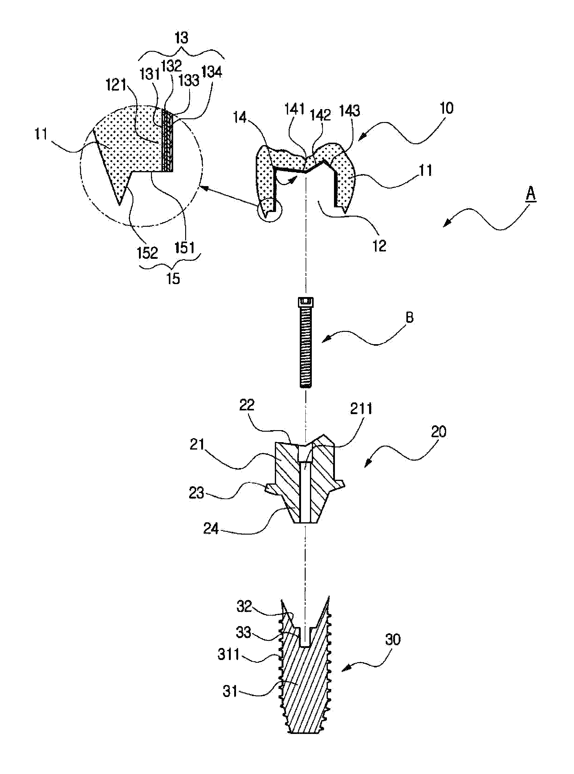
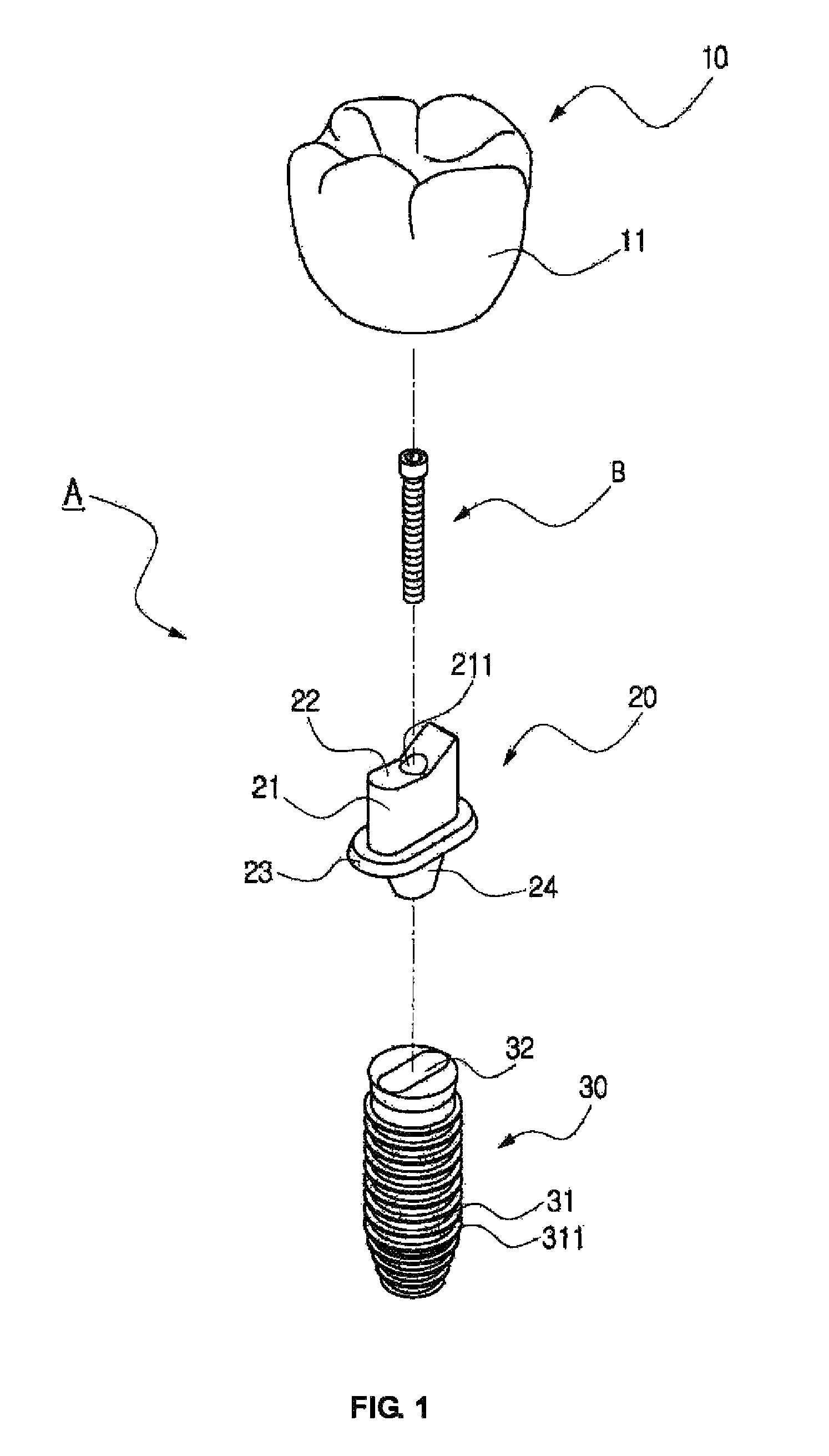
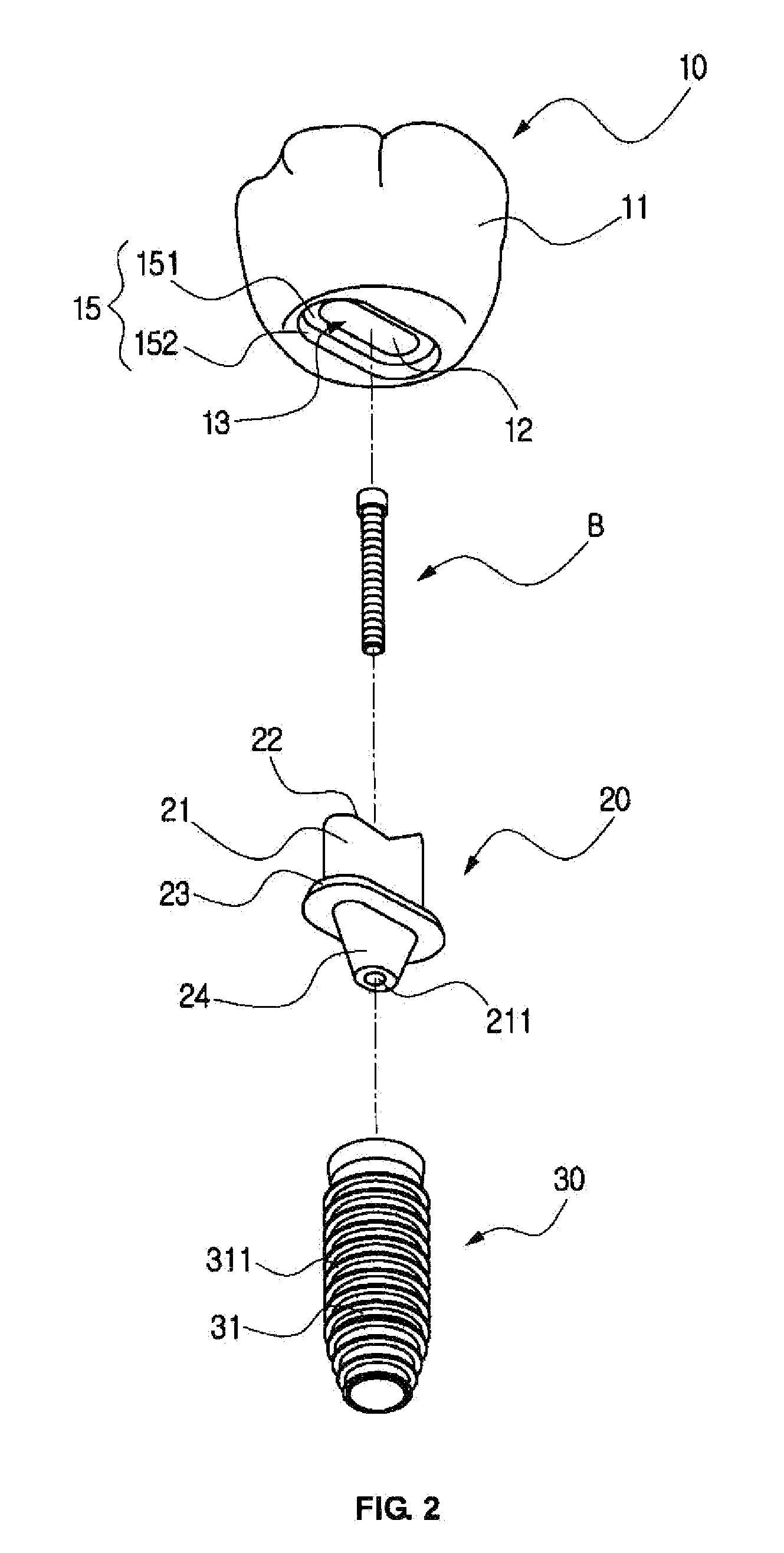
[0031]As shown in FIGS. 1 to 5, a functional implant A according to the present invention includes a fixture 30 screw-coupled to a tooth extraction hole 61 formed on an alveolar bone 60, an abutment 20 coupled to the fixture 30 by means of a bolt B in such a manner as to allow the lower portion thereof to be fitted to the upper portion of the fixture 30, and a crown 10 detachably coupled to the abutment 20 coupled to the fixture 30 by means of the bolt B.

[0032]In this case, the crown 10 is formed by means of milling so as to have the same shape as the existing tooth and has a crown body 11 and an abutment insertion recess 12 formed inside the crown body 11 in such a manner as to be open on the underside of the crown body 11.

[0033]The crown 10 is made of zirconium dioxide ZrO2 and concave on the center of the upper portion thereo...


PUM

PropertyMeasurementUnit
heightaaaaaaaaaa
sizesaaaaaaaaaa
thicknessaaaaaaaaaa

Abstract

A functional implant includes: a fixture; an abutment coupled to the upper portion of the fixture using a bolt; and a crown coupled to the abutment coupled to the fixture, the crown having a crown body concave on top thereof, an abutment insertion recess formed inside the crown body to be open on the underside of the crown body, and a coupling guide portion formed on an inner peripheral wall of the abutment insertion recess and having a scratch surface formed on the surface of the inner peripheral wall, a silica layer bonded to the scratch surface, a zirconia primer layer coated onto the silica layer, and a resin bonded to the zirconia primer layer. The crown is detachably coupled to the abutment through press-fitting, thereby allowing easy detachment and smooth repair and correction. The crown is made using milling, thus reducing errors to ensure good fitness and passivity.

Description

TECHNICAL FIELD[0001]The present invention relates to a functional implant, and more particularly, to a functional implant that is provided with a crown having an abutment insertion recess formed inside a crown body and a coupling guide portion formed on an inner peripheral wall of the abutment insertion recess through the sequential application of a scratch surface, a silica layer, a zirconia primer layer, and a resin to the inner peripheral wall of the abutment insertion recess, so that the crown is detachably coupled to an abutment.BACKGROUND ART[0002]Generally, an implant is an artificial tooth root made of a material having no rejection reaction to the human body, which is placed into an alveolar bone from which a tooth is missing to replace the root of the missing tooth therewith, and after the artificial tooth root is integral into the alveolar bone, an artificial tooth is fixed to the artificial tooth root through a connection post, thus restoring the original function of th...

Claims


Application Information

Patent Timeline
Patent Type & Authority Patents(United States)
IPC IPC(8): A61C5/10A61C5/08A61C13/09A61C8/00A61K6/08A61K6/884
CPCA61C8/0086A61K6/08A61C8/0048A61C8/0068A61C8/0066A61C5/08A61C5/10A61C8/0013A61C8/0022A61C5/70A61C5/77
Inventor KIM, YONG HYEOP
Owner HIGH DENTAL KOREA
Why Eureka
Try Eureka