
Cryogenic liquid turbine

a cryogenic liquid turbine and liquid expansion chamber technology, applied in machines/engines, renewable energy generation, greenhouse gas reduction, etc., can solve the problems of increasing the cold loss reducing the efficiency of the liquid expansion chamber, and large loss through the nozzle chassis, so as to reduce the vaporization rate

Active Publication Date: 2017-01-03
XI AN JIAOTONG UNIV
View PDF8 Cites 0 Cited by
  • Summary
  • Abstract
  • Description
  • Claims
  • Application Information

AI Technical Summary

Benefits of technology

[0007]An object of the present invention is to provide a cryogenic liquid turbine for throttling low-temperature and high-pressure liquefied gases, so as to overcome disadvantages such as considerable cold loss, considerable flow loss at impeller outlet, and the structure of the whole machine is difficult to be orientated and installed. The cryogenic liquid turbine replaces the liquid Joule-Thompson valves conventionally used in the large-scale energy consumption low temperature cycle devices of air separation, liquefied natural gas (LNG), etc. to reduce vaporization rate and recover high-level pressure head of the throttled liquefied gases.
[0018]The shaft is rotatably fixed in the machine casing by two thrust journal bearings; two ends of the shaft are both in a form of triangular polygon; one end of the shaft is connected to the impeller by a fastening screw; the other end of the shaft is connected to the coupling; a generator, a pump, or an air blower can be used to brake; and the rotor avoids an oil seal of oil slinger ring structure, in such a manner that rotating parts are reduced and operation reliability of the machine is enhanced.
[0019]A cold barrier structure is realized mainly by positioning the nozzle assembly in the volute; the volute is put into a perlite cold box for thermal insulation; an insulating pad is applied between the volute and the machine housing to insulate the heat; in such a manner that a low temperature liquid is not directly contacted to the machine housing exposed in an atmospheric environment, so a coldness loss is decreased to a maximum extent.
[0029]The diffuser pipe is fixed and installed axially with the volute to reduce flow velocity at impeller outlet and reduce flow loss. A shroud side seal is axially fixed on the nozzle compression flange; a shaft seal is fixed with the seal gas part; the seal gas part and the oil seal are both axially fixed on the machine housing by a orientating bolt for easy axial positioning and assembling the machine units.
[0030]In comparison with the existing technology of the cryogenic liquid turbine, advantages of the present invention are as follows. (1) effective cold barrier structure is used, in such a manner that the coldness loss of the machine is reduced effectively, and efficiency of energy utilization is enhanced, which reduces the power consumption of a low temperature air separation device and a low temperature liquefied device. (2) the present invention uses the diffuser pipe at the impeller outlet, in such a manner that the impeller outlet velocity is effectively reduced, and thus the flow loss is reduced. (3) the present invention modifies the structures of several related parts, which provides the convenience for orientating and installing axially the parts of the machine

Problems solved by technology

However, “Liquid expander” has disadvantages as follows.
Therefore, the cold loss through the nozzle chassis is very large, which decreases the efficiency of the liquid expander.
In addition, the liquid expander uses the nozzle adjusting mechanism that gets through the nozzle chassis, which also increases the cold loss of the liquid expander and causes a result that the nozzle adjusting mechanism cannot be operated normally.
2) the nozzle cover plate is connected to the nozzle chassis only by the pin, and the compression margin of the compression spring of the nozzle cannot be adjusted, which increases the difficulty of orientation and installation in the axial direction while the precision is difficult to be guaranteed.
3) the diffuser tube of the impeller outlet and the nozzle assembly are manufactured as a whole, which increases the difficulty of axially orientating the complete machine.
4) the impeller outlet does not use any effective device for decelerating high-velocity media and subsequently raising its pressure, so at the impeller outlet, media velocity is high and the flow loss is large.
1) the structure that turbine rotor and generator rotor are coaxial is used, so the impeller is of the same size as the generator and the volume of the complete machine is relatively large, which is only appropriate for applications of large flow rates; 2) the generator is completely immersed in low temperature media, so the requirement of cable materials of the generator, the requirement of the sealing performance of the generator, and the requirement of the insulating property of the generator are stringent; 3) the braking method is not flexible, wherein only electrical generator may be utilized for braking, and the submerged liquid turbine is not appropriate for using air blower and pump to brake.

Method used


Image

  • Cryogenic liquid turbine
  • Cryogenic liquid turbine

Examples


Embodiment Construction

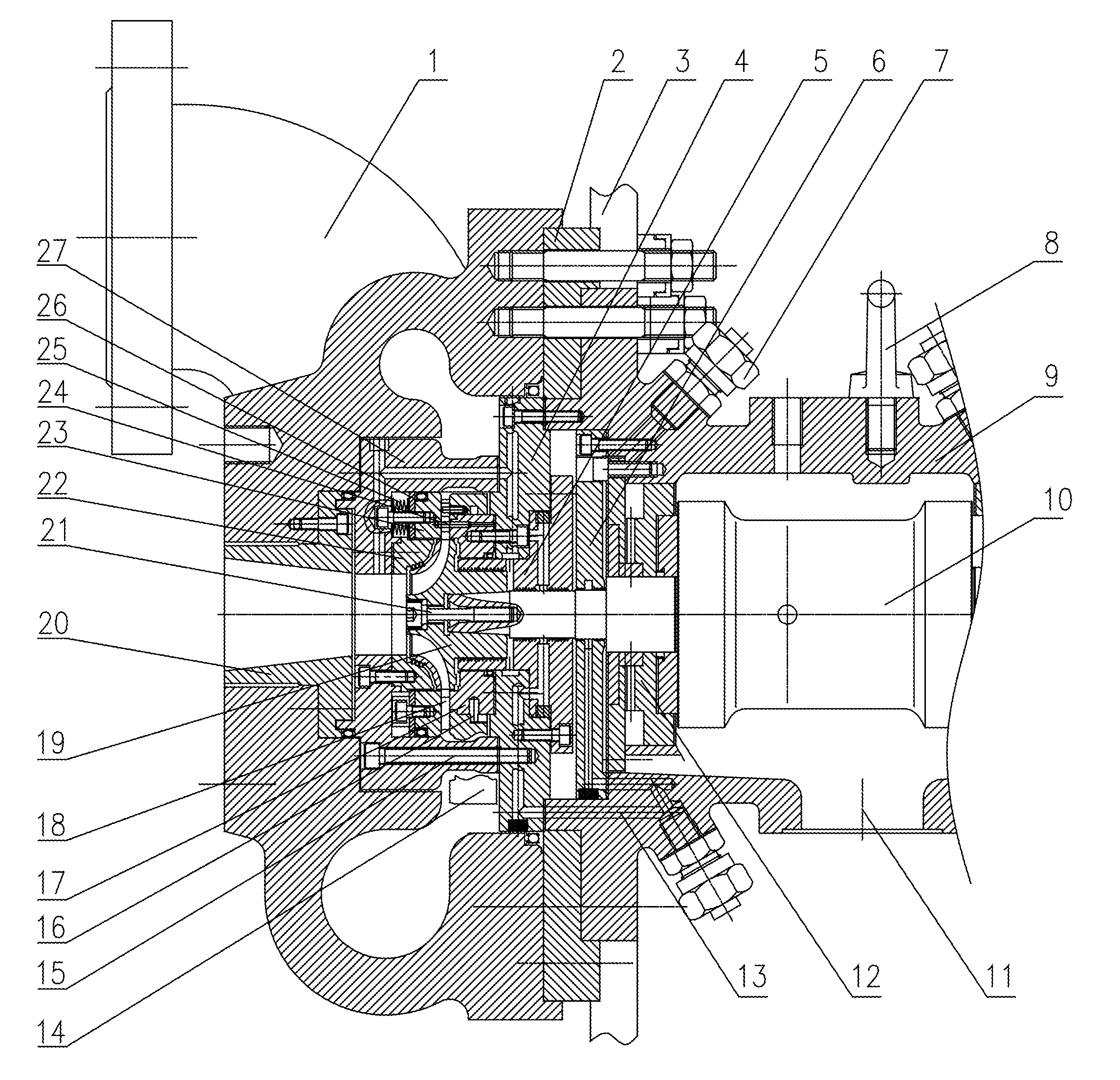
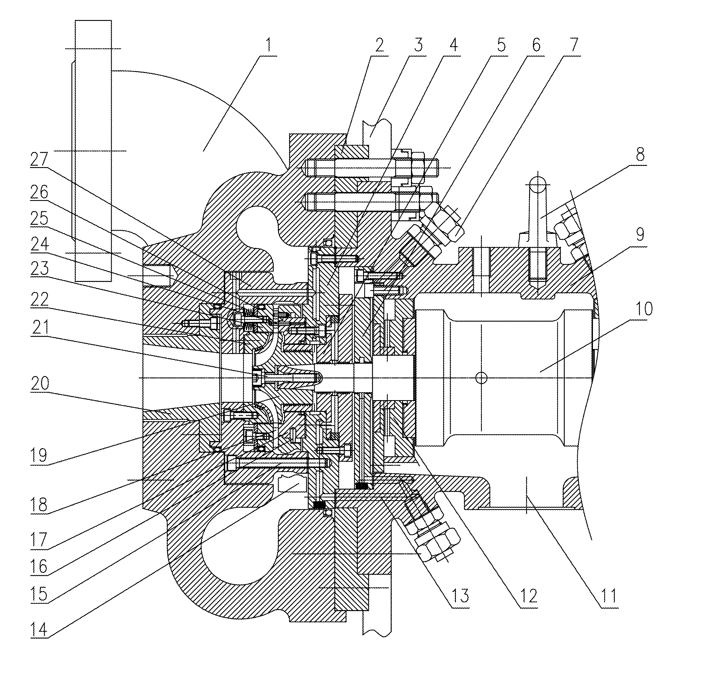
[0060]Referring to FIGURE and embodiments, the present invention is further described in details as follows.

[0061]Referring to the FIGURE, a cryogenic liquid turbine comprises:[0062]a machine housing 9,[0063]a thrust journal bearings 12,[0064]a rotor,[0065]a nozzle unit,[0066]a volute 1,[0067]a diffuser pipe 20,[0068]a sealing element, and[0069]a cold box 3;

wherein, the machine housing 9 comprises:[0070]a lifting eye bolt 8,[0071]an oil outlet 11,[0072]a bearing temperature measuring hole,[0073]a bearing oil supplying hole and[0074]an air supplying hole of a gas seal,[0075]which are all connected by a connector 7 to corresponding pipelines;

wherein the rotor comprises:[0076]a shaft 10,[0077]an impeller 19,[0078]and a coupling;

wherein the nozzle assembly comprises:[0079]a nozzle turntable 14,[0080]a nozzle chassis 17,[0081]a nozzle cover plate 23,[0082]a nozzle compression plate 26,[0083]a nozzle compression flange 27,[0084]nozzle vanes 18, and[0085]a nozzle adjusting mechanism;

wherei...


PUM


Abstract

A cryogenic liquid turbine is provided, wherein, impeller end of the rotor and nozzle assembly are received into cavity of volute, and main part of the volute is put into perlite cold box; insulation pad is used between the volute and machine housing to insulate heat; impeller outlet is connected to diffuser pipe. A nozzle assembly is connected to the machine housing by a nozzle compression flange; a nozzle compression plate adjusts a compactness of nozzle vanes by a disc spring; a nozzle turntable is connected on a nozzle chassis, and adjusts the nozzle vane stagger angle by adjusting mechanism passing through the volute; impeller shroud side seal is axially fixed on the nozzle compression flange, and a shaft seal is axially fixed to a seal gas part; the seal gas part and an oil seal are axially fixed to the machine housing by a bolt.

Description

CROSS REFERENCE OF RELATED APPLICATION[0001]This is a U.S. National Stage under 35 U.S.C. 371 of the International Application PCT / CN2011 / 085009, filed Dec. 30, 2011.BACKGROUND OF THE PRESENT INVENTION[0002]Field of Invention[0003]The present invention belongs to the wasted pressure recovery technology in fields of cryogenic liquefaction and cryogenic air separation, relates to a radial-axial type cryogenic liquid turbine, and more particularly to a cryogenic liquid turbine for throttling and decompressing low-temperature and high-pressure liquefied gases.[0004]Description of Related Arts[0005]Energy saving is the main part of and guarantee for the sustainable development strategy of global economy, and can effectively relieve the restriction of the energy bottleneck, so as to help to establish the energy-saving society. Recovering industrial wasted energy in large-scale energy consumption apparatuses is one of key measures of the energy saving, and has great social benefit and econ...

Claims


Application Information

Patent Timeline
Patent Type & Authority Patents(United States)
IPC IPC(8): F03B3/02F01D17/16F01D9/02F01D1/08F03B11/00F01D5/02F03B11/02F03B3/18F01D25/14
CPCF03B3/02F01D1/08F01D5/025F01D9/026F01D17/165F01D25/145F03B3/183F03B11/006F03B11/02F05B2210/11F05D2210/11F05D2250/131Y02E10/223Y02E10/226Y02E10/20
Inventor SUN, JINJUWANG, KESONG, PENG
Owner XI AN JIAOTONG UNIV
Learn More