
Process for efficiently converting green electricity into low-energy-consumption air separation energy storage and purifying and liquefying CO2

A low-energy, high-efficiency technology, applied in liquefaction, refrigeration, liquefaction, solidification, etc., can solve the problems of restricting the large-scale development of renewable energy, not being effectively utilized, and the difficulty of heavy oil production, so as to avoid oxygen corrosion on the well wall , efficient conversion and utilization, and the effect of improving fuel utilization

Active Publication Date: 2022-07-26
HANGZHOU TURNING ENERGY TECH DEV CO LTD
View PDF5 Cites 0 Cited by
  • Summary
  • Abstract
  • Description
  • Claims
  • Application Information

AI Technical Summary

Problems solved by technology

However, wind power generation, solar power generation, etc. belong to intermittent energy generation. How to efficiently and reasonably store and utilize this part of energy has become a key technical bottleneck restricting the large-scale development of renewable energy.
[0003]At the same time, in the process of oil extraction, oilfield mining companies encounter difficulties in the extraction of heavy oil, low oil recovery rate, and the combustion of gas-fired boilers or coal-fired boilers will produce a large amount of CO2, has not been effectively utilized, and the original nitrogen production by adsorption method needs to be solved urgently due to the high oxygen content in nitrogen, which will cause oxygen corrosion on the well wall

Method used


Image

  • Process for efficiently converting green electricity into low-energy-consumption air separation energy storage and purifying and liquefying CO2

Examples


Embodiment Construction

[0044] The present invention will be further explained below with reference to the embodiments and the accompanying drawings. The following examples are only used to illustrate the present invention, but are not intended to limit the scope of implementation of the present invention.

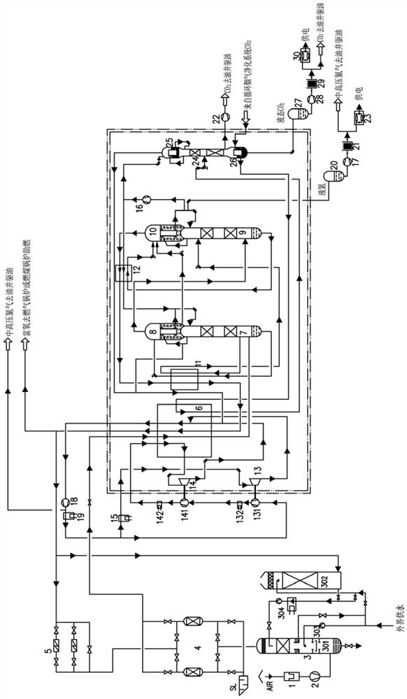
[0045] A high-efficiency conversion of green electricity to low-energy air separation energy storage and CO 2 Purification and liquefaction process, the equipment required for the process is such as figure 1 As shown, including filter 1, air compressor 2, air pre-cooling system 3, alternately used molecular sieve adsorber 4, electric heater 5, main heat exchanger 6, rectifying tower 17, main condensing evaporator 18, Cooler I11, rectification tower II9, main condensing evaporator II10, subcooler II12, high temperature expander 13, low temperature expander 14, low temperature freezer 15, liquid nitrogen pump I16, circulating nitrogen compressor 18, circulating nitrogen compressor After water coo...


PUM


Abstract

The invention discloses a process for efficiently converting green electricity into low-energy-consumption air separation energy storage and purifying and liquefying CO2. The required device comprises a filter, an air compressor, an air pre-cooling system, a molecular sieve adsorber, an electric heater, a main heat exchanger, rectifying towers I and II, main condensation evaporators I, II, III and IV, subcoolers I and II, a high-temperature expansion machine, a low-temperature expansion machine, a low-temperature refrigerator, a liquid nitrogen pump I, a circulating nitrogen compressor, a water cooler behind the circulating nitrogen compressor, a liquid nitrogen storage tank, a CO2 rectifying tower, a CO2 supercharger and a liquid CO2 storage tank, wherein the molecular sieve adsorber, the electric heater, the main heat exchanger, the rectifying towers I and II, the main condensation evaporators I, II, III and IV are alternately used. According to the invention, medium and high pressure nitrogen, high purity rich oxygen and liquid nitrogen are prepared by using green electricity, CO2 enriched and purified by a circulating flue gas purification system is purified and liquefied to prepare gaseous and liquid CO2 products, the medium and high pressure nitrogen and the gaseous CO2 products are subjected to oil displacement in an oil well, the green electricity is stored in a liquid form by the liquid nitrogen and the liquid CO2 products, and the green electricity is subjected to oil displacement in the oil well and / or expansion power generation after being pressurized and vaporized. And efficient conversion and utilization of green electricity are realized.

Description

technical field [0001] The invention relates to the technical field of air separation energy storage, in particular to a low energy consumption air separation energy storage and CO 2 Purification liquefaction process. Background technique [0002] The promotion and application of renewable energy technologies such as wind energy and solar energy is imminent. However, wind power, solar power, etc. belong to intermittent energy generation. How to efficiently and reasonably store and utilize this part of energy has become a key technical bottleneck restricting the large-scale development of renewable energy. [0003] At the same time, oilfield mining enterprises encounter difficulties in the extraction of heavy oil, low oil recovery rate, and combustion of gas-fired boilers or coal-fired boilers, which will generate a large amount of CO. 2 , has not been effectively used, the original nitrogen production by adsorption method will cause oxygen corrosion of the well wall due to...

Claims


Application Information

Patent Timeline
Patent Type & Authority Applications(China)
IPC IPC(8): F25J3/04F25J3/08
CPCF25J3/04024F25J3/04084F25J3/04109F25J3/08F25J3/04424F25J2205/32F25J3/04393F25J3/04581F25J3/04569F25J2270/90F25J2200/20F25J3/0423F25J3/04157F25J2245/42F25J3/04278F25J2260/30F25J2205/34F25J2250/42F25J3/04357F25J2235/42F25J3/04612F25J2210/70F25J2260/80F25J2210/80
Inventor 韦霆于莎莎何森林
Owner HANGZHOU TURNING ENERGY TECH DEV CO LTD
Learn More