
An electronic expansion valve

An electronic expansion valve and valve seat technology, which is applied in the field of control valves, can solve the problems of increased refrigerant turbulence intensity, refrigerant flow noise, and increased refrigerant noise, and achieve the effects of reducing turbulence intensity, reducing noise, and reducing flow sound

Active Publication Date: 2019-08-20
ZHEJIANG SANHUA INTELLIGENT CONTROLS CO LTD
View PDF6 Cites 0 Cited by
  • Summary
  • Abstract
  • Description
  • Claims
  • Application Information

AI Technical Summary

Problems solved by technology

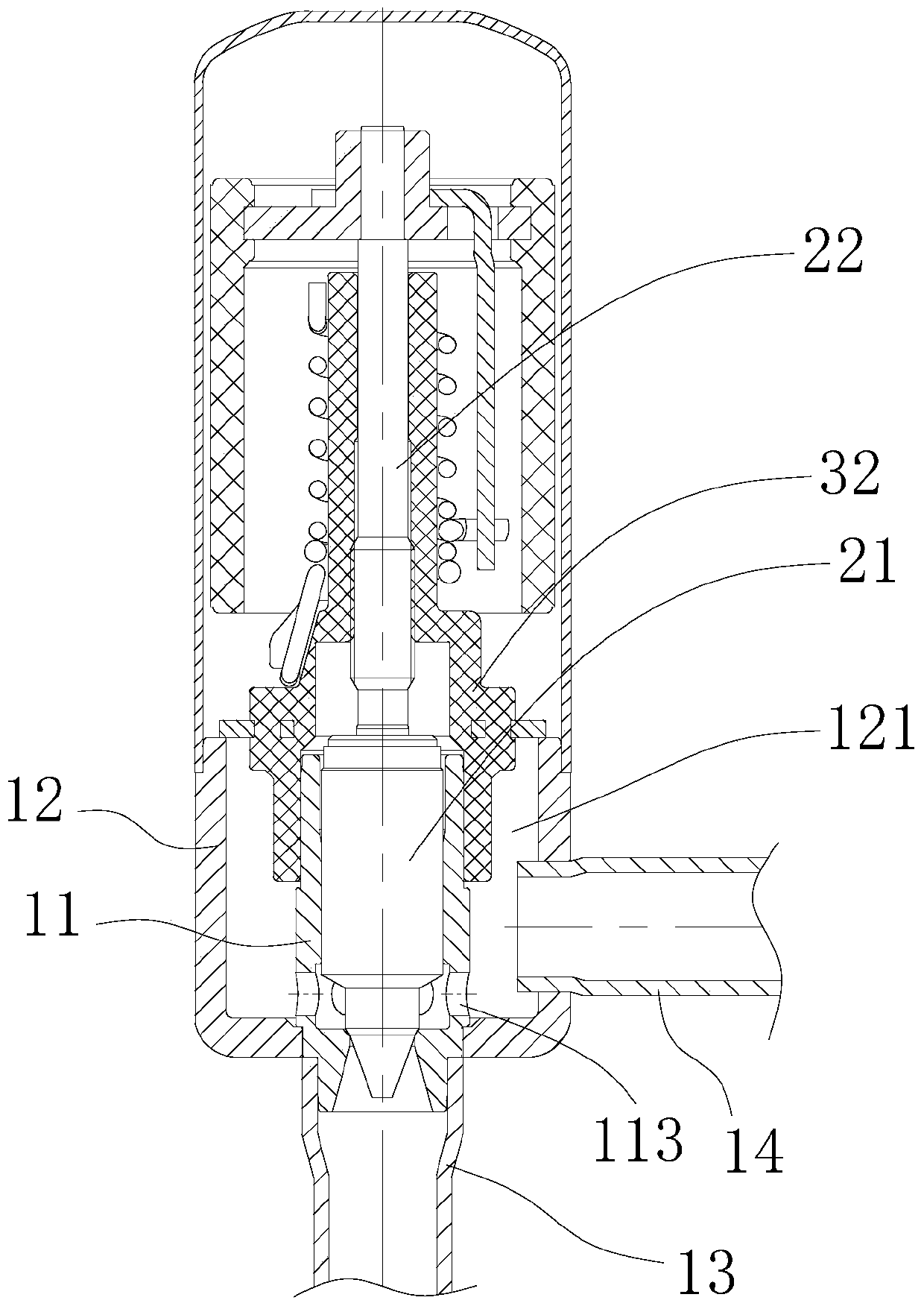
[0006] In this technical solution, the noise of the refrigerant fluid can be reduced to a certain extent during the forward flow process, but when the fluid flows in the reverse direction, after the fluid flows out from the communication hole on the circumference of the valve core seat 11, due to the valve core seat 11 and the valve If the first valve cavity 121 between the seats 12 is too large, the fluid will expand greatly and part of the gas will be evaporated, and the gas may be mixed in the liquid refrigerant to form cavitation, thus generating the noise of refrigerant flow
At the same time, after flowing out from the communication hole of the valve core seat 11, and then flowing into the second connecting pipe 14, there is no guiding flow path between the two, and the fluid will flow chaotically, which is prone to turbulence, and turbulence is the generation of fluid noise. important factor
Regardless of whether it is forward flow or reverse flow, the direction of refrigerant flow in the first valve cavity will inevitably become a chaotic movement, the intensity of refrigerant turbulence will increase, and the noise of refrigerant will also increase.

Method used


Image

  • An electronic expansion valve
  • An electronic expansion valve
  • An electronic expansion valve

Examples


Embodiment Construction

[0031] In order to enable those skilled in the art to better understand the technical solutions of the present invention, the present invention will be further described in detail below in conjunction with the accompanying drawings and specific embodiments.

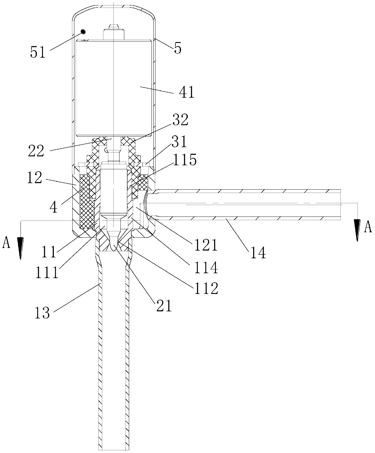
[0032] Please refer to figure 2 , figure 2 It is a structural schematic diagram of the electronic expansion valve provided by the present invention.

[0033] The electronic expansion valve provided by the present invention includes a valve seat assembly, a nut assembly, a valve needle screw assembly, a magnetic rotor assembly and a coil assembly.

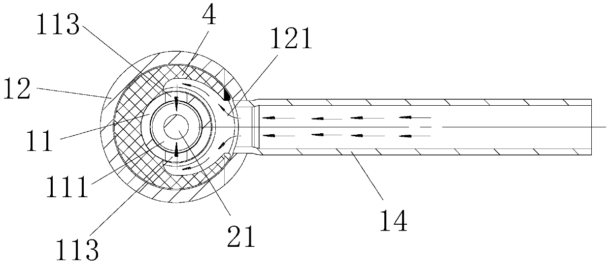
[0034] The valve seat assembly includes a valve core seat 11 and a valve seat 12 . The valve seat 12 is a substantially cylindrical structure with a matching hole on the bottom of the valve core seat, and a first valve cavity 121 is formed inside it. In this embodiment, the valve seat assembly further includes a first connecting pipe 13 and a second connecting pipe 14 . T...


PUM


Abstract

An electronic expansion valve, characterized in that it includes a valve seat provided with a first valve cavity and a substantially cylindrical valve core seat, a second valve cavity is formed inside the valve core seat; it is connected and fixed to the valve seat The first connecting pipe and the second connecting pipe; the circumferential side wall of the valve core seat is provided with a communication hole, and the communication hole communicates the second valve chamber with the first valve chamber; it is arranged inside the valve body The nut; also includes a guiding flow path component, the guiding flow path component is arranged in the first cavity, so that the refrigerant flow path from the communication hole to the second connecting pipe gradually expands. In the electronic expansion valve provided by the present invention, the effective cavity formed by the valve seat is reduced by setting the guide flow path components in the first cavity, which avoids excessive expansion of the fluid, thereby reducing the probability of fluid vaporization and suppressing cavitation. Formation; avoiding popping sounds during fluid flow and reducing noise.

Description

technical field [0001] The invention relates to the technical field of control valves, in particular to an electronic expansion valve for regulating fluid flow. Background technique [0002] In various refrigeration and heating equipment such as air conditioners, refrigerators, heat pump water heaters, etc., electronic expansion valves are usually used to regulate the flow of fluids. In addition, the electronic expansion valve can also be used as a pilot valve in the solenoid valve. Its basic working principle is to adjust the gas / liquid flow by controlling the opening of the electronic expansion valve, so as to realize the system function and achieve the purpose of precise control. [0003] The electronic expansion valve usually includes a valve seat assembly, a nut assembly, a valve needle screw assembly, and a rotor assembly. The valve seat assembly usually includes a valve seat and a connecting pipe. The valve seat has a valve port, and the valve seat and the connecting ...

Claims


Application Information

Patent Timeline
Patent Type & Authority Patents(China)
IPC IPC(8): F16K1/00F16K47/02F25B41/06F25B41/34
CPCF16K1/00F16K47/02F25B41/31Y02B30/70
Inventor 不公告发明人
Owner ZHEJIANG SANHUA INTELLIGENT CONTROLS CO LTD
Learn More