Steering gear

Active Publication Date: 2017-01-03
ROBERT BOSCH AUTOMOTIVE STEERING
View PDF17 Cites 4 Cited by
  • Summary
  • Abstract
  • Description
  • Claims
  • Application Information

AI Technical Summary

Benefits of technology

[0018]In order to bring about the most uniform possible transmission or axial forces between the pivoting ring and the shaped bearing bushing there can advantageously be provision of an annular washer which is arranged between the pivoting ring and the outer collar.

Problems solved by technology

However, in order to mount the pinion shaft in the fixed bearing with as little play as possible, this inventive solution requires the movement of the pinion shaft to be transmitted with as little play as possible from said pinion shaft to the rotary bearing and then to the pivoting ring via the bearing bushing.

Method used


Image

  • Steering gear
  • Steering gear
  • Steering gear

Examples


Embodiment Construction

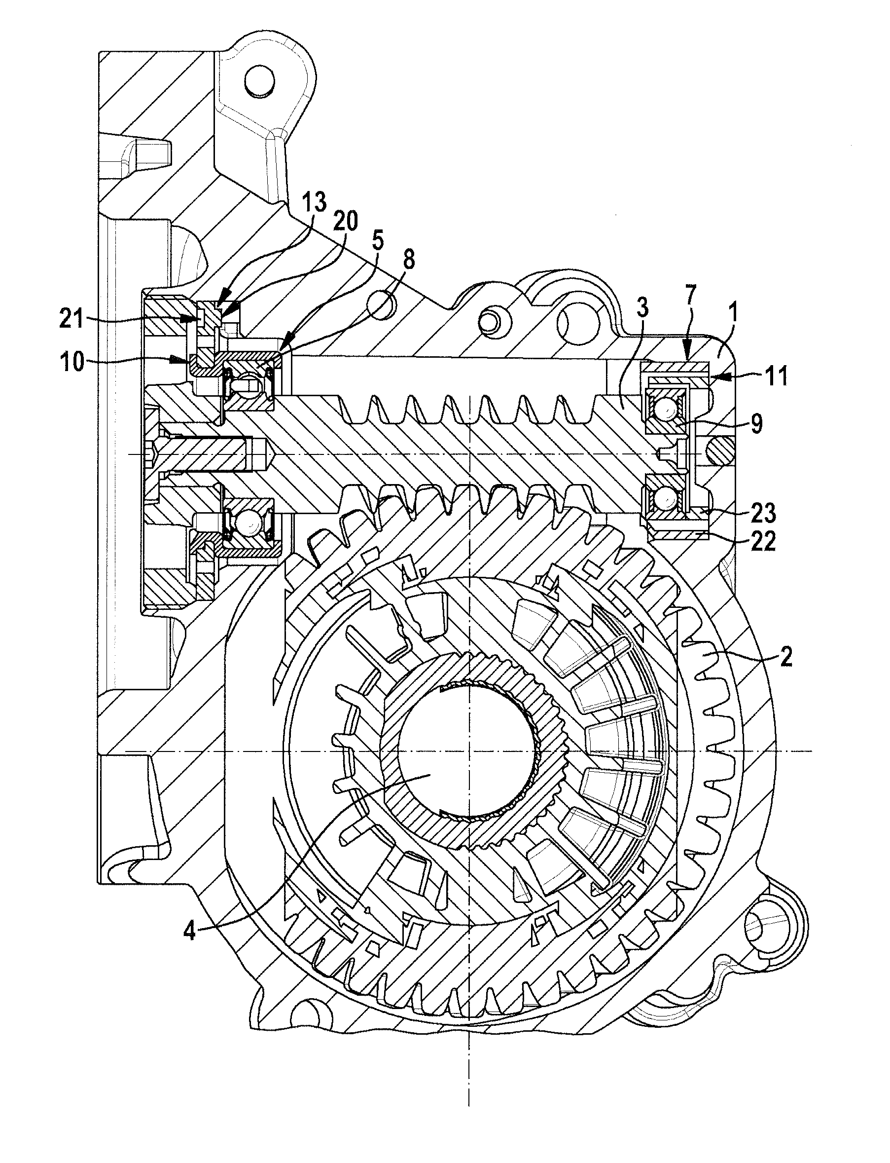
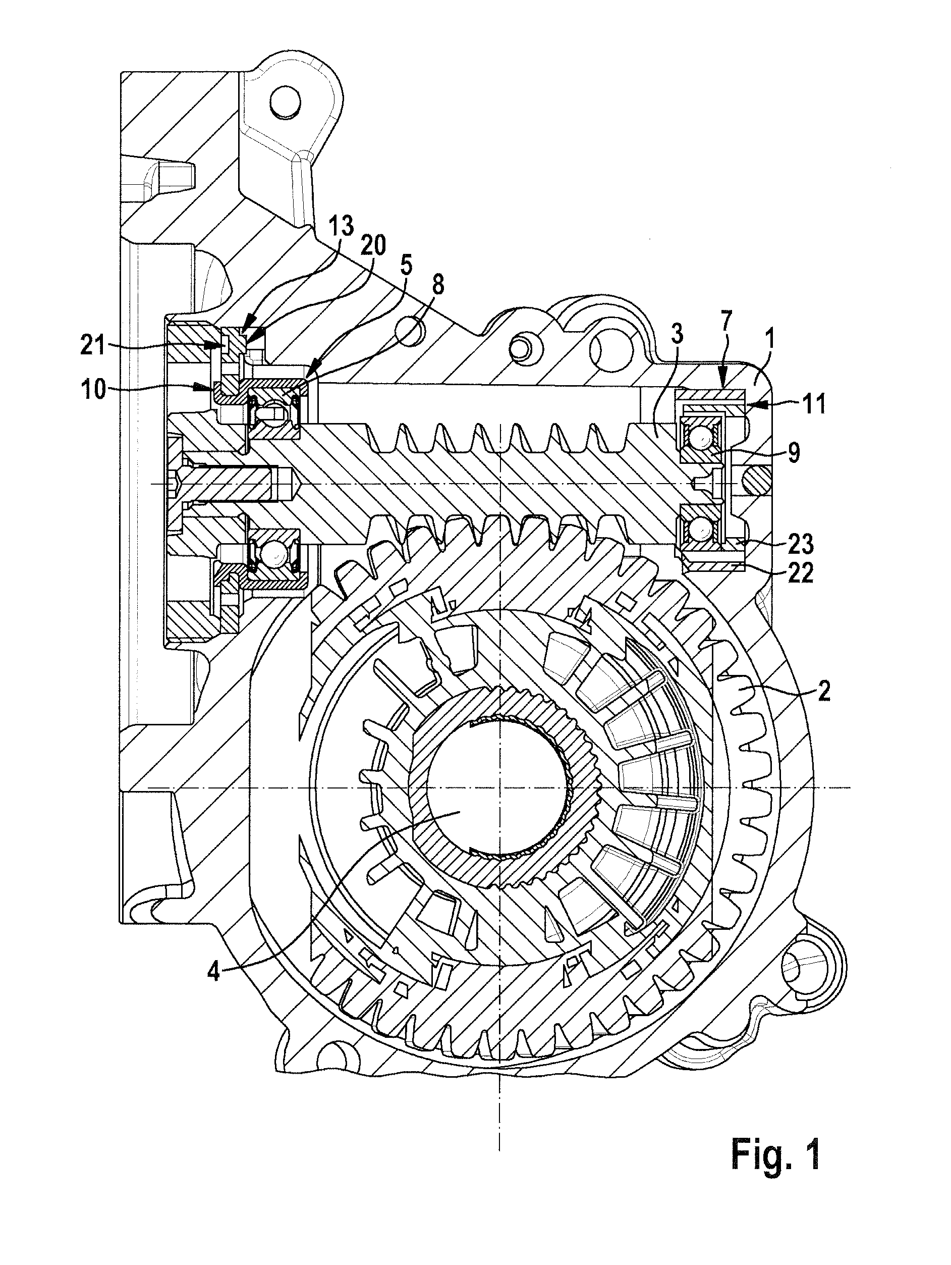
[0026]FIG. 1 shows the essential components of an embodiment of a steering gear according to the invention. The latter comprises a housing 1, within which a gear wheel 2 and a pinion which meshes with the gear wheel 2 are mounted. The pinion and a pinion shaft 3 which comprises the pinion are constructed integrally in the form of a worm.

[0027]The gear wheel 2 is fixedly attached to a steering column 4 or to an output shaft of the steering gear of a motor vehicle.

[0028]The pinion shaft 3 has a drive-side end by means of which it is able to be connected to the output shaft of a drive (for example an electric motor) which is not shown. In the region of this drive-side end, the pinion shaft 3 is mounted in the housing 1 by means of a first bearing arrangement. This bearing arrangement is embodied as a fixed bearing 5 which essentially permits no translation of the pinion shaft 3 relative to the housing 1, but does permit pivoting about a pivoting axis 6.

[0029]This pivoting causes the fr...


PUM


Abstract

A fixed bearing for a steering gear having a rotary bearing which comprises an inner bearing shell which is provided for receiving a pinion shaft of the steering gear, and an outer bearing shell which is accommodated in a bearing bushing, and having a pivoting ring which has an outer ring and an inner ring which are pivotably connected via one or more torsion webs, wherein the outer ring is provided for supporting the fixed bearing in a housing of the steering gear, wherein the inner ring of the pivoting ring is mounted and axially secured on the outside of the bearing bushing.

Description

BACKGROUND OF THE INVENTION[0001]The invention relates to a steering gear for a power-assisted steering system of a motor vehicle, and in particular a fixed bearing for such a steering gear.[0002]In most motor vehicles, power-assisted steering systems are installed which generate a supporting torque during steering and as a result reduce the steering torque which has to be applied to the steering column by the driver.[0003]The known power-assisted steering systems are based on a steering gear which converts the driving power of a hydraulic or electric drive and transmits it to the steering column. Such steering gears are generally embodied in the form of a screw rolling gear, and in particular as a helical gear or worm gear, i.e. the latter comprise a gear wheel which is connected directly or indirectly to the steering rod, and a pinion which meshes therewith and is driven by the drive via a pinion shaft.[0004]Gearing play which is formed owing to component tolerances, different wid...

Claims


Application Information

Patent Timeline
Patent Type & Authority Patents(United States)
IPC IPC(8): F16H1/16F16C27/04F16H57/039B62D5/04F16C19/54F16H57/022F16H57/12F16C19/06F16H25/24F16H57/021
CPCF16C27/04B62D5/0409F16H57/039F16C19/06F16C19/54F16H25/24F16H2057/0213F16H2057/0222F16H2057/127F16C2226/50F16C2326/24F16C2361/61B62D3/02B62D5/00F16C35/06
Inventor HAFERMALZ, JENSFUECHSEL, DENNIS
Owner ROBERT BOSCH AUTOMOTIVE STEERING
Why Eureka
Try Eureka