Chain guide

a technology of chain guide and chain loop, which is applied in the direction of belt/chain/gearing, mechanical equipment, belt/chain/gearing, etc., can solve the problems of bolt loosening and falling out, cracks or fractures in the base, and increase production costs, so as to facilitate assembly and maintenance. operation, cost reduction

Inactive Publication Date: 2017-01-03
TSUBAKIMOTO CHAIN CO
View PDF16 Cites 3 Cited by
  • Summary
  • Abstract
  • Description
  • Claims
  • Application Information

AI Technical Summary

Benefits of technology

[0018]Further, in the boundary zone of the shoe support portion 521 and the vicinity of the center of the two base mounting portions 522, which are constituted by the integral metal sheet of the base member 520, internal stresses are concentrated during the bending operation and stress concentration easily occurs during the use. The resultant problem is that cracks and breaks easily occur and the sheet thickness should be increased. Further, since the two base mounting portions 522 constituted by the integral metal sheet of the base member 520 are present at the same side surface, the pushing pressure of the chain creates a cantilever support during the use, thereby creating a load offset and also making it necessary to increase the sheet thickness in order to ensure a sufficient support. Further, since the two base mounting portions 522 should be fixed with bolts or the like to the engine, vibrations or noise generated in the base member 520 by the running chain are easily transmitted to the engine, and vibrations or noise of the entire engine are increased.
[0043]In addition, no concentrated stresses are applied to the base mounting portion or the guide shoe mounting portion, the fixed components can be reliably prevented from loosening, vibrations and noise can be prevented from increasing during the use, and the maintenance operation load can be reduced.

Problems solved by technology

The resultant problem is that where the accuracy of the two bent portions is low, strains appear in the base member 520 when it is fixed with bolts or the like to an engine or the like, the bolts can get loose and fall out due to running or engine vibrations, and cracks or fractures can appear in the base member 520 itself.
Where the bending processing is performed with a high accuracy to avoid the aforementioned problem, the production cost rises.
The resultant problem is that cracks and breaks easily occur and the sheet thickness should be increased.
The resultant problem is that specifications of a punching die or bending machine should be changed, which requires time and increases cost, and the degree of design freedom is low.

Method used


Image

  • Chain guide
  • Chain guide
  • Chain guide

Examples


example 1

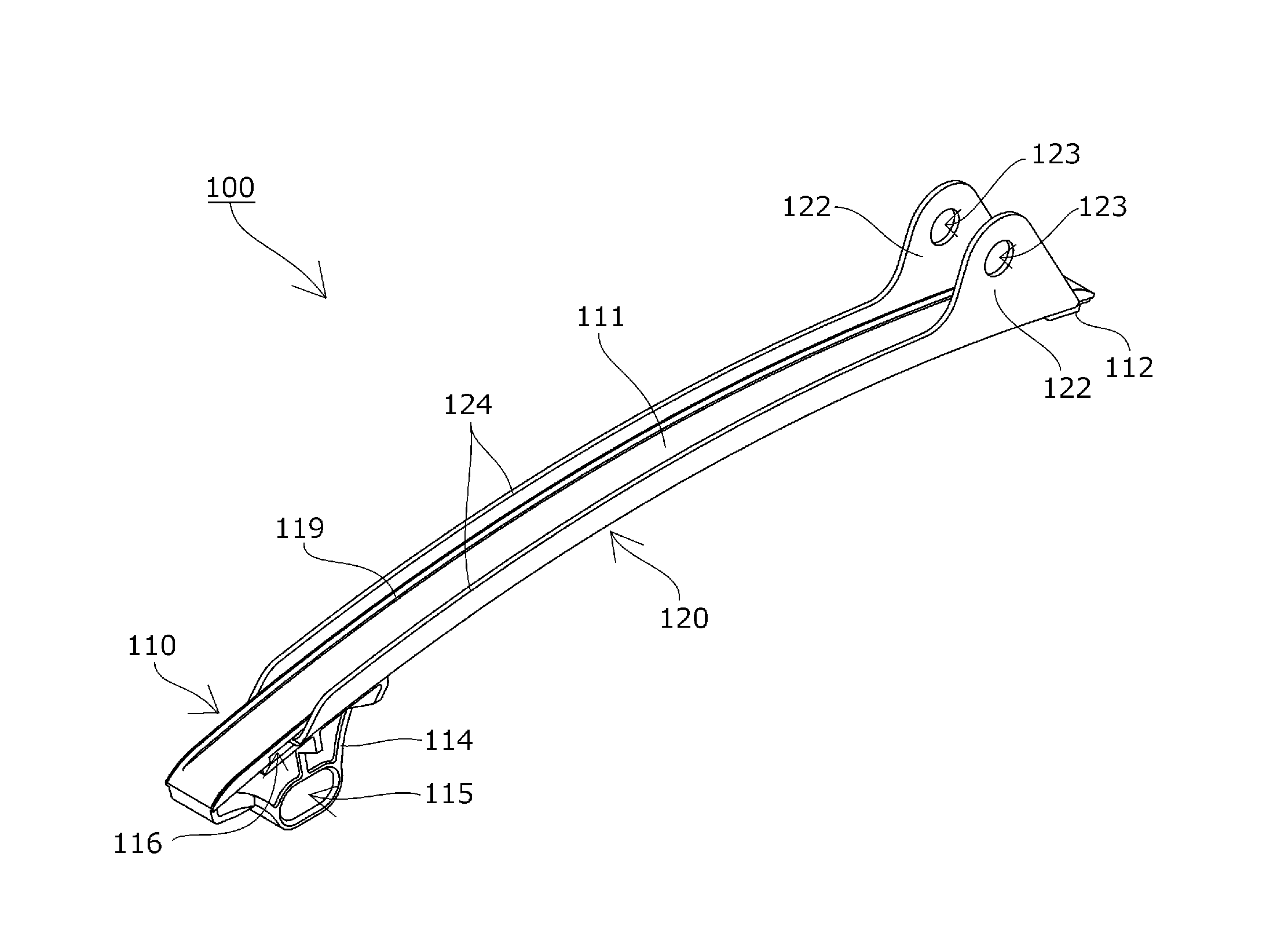
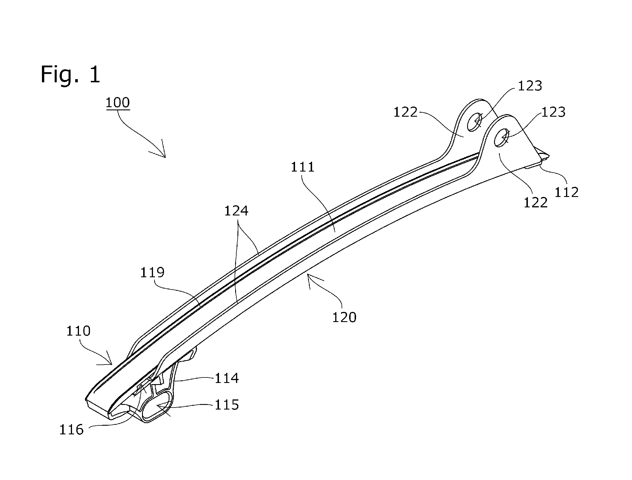
[0066]A chain guide 100 (fixed guide) according to the first embodiment of the present invention will be explained hereinbelow with reference to the appended drawings.

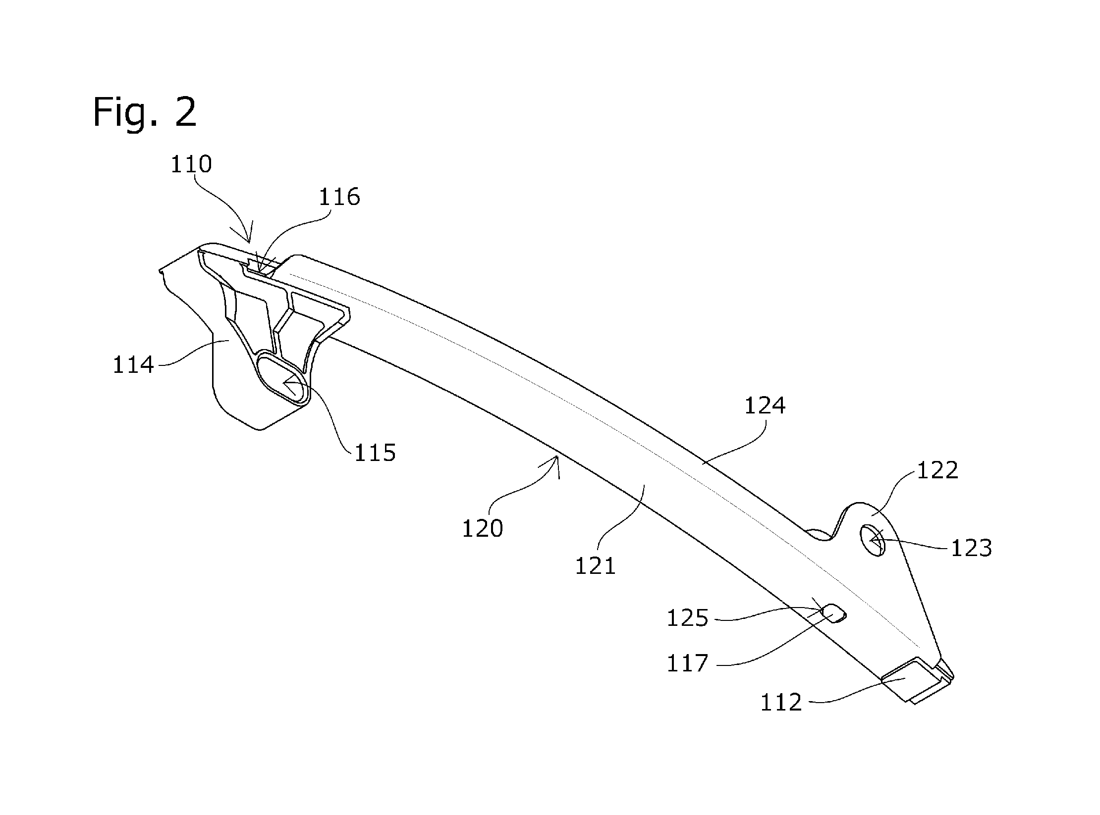
[0067]The chain guide 100 is suitable for the above-described well-known timing system and includes, as shown in FIGS. 1 to 3, a guide shoe 110 slidingly guiding a running chain and a base member 120 supporting the guide shoe 110 along the chain running direction.

[0068]The base member 120 includes a shoe support portion 121 extending in the chain running direction, two parallel base mounting portions 122 extending vertically to the chain running direction from both sides in the width direction, and two parallel base wall portions 124 provided at both sides in the width direction. The base member is formed by punching from a single rolled steel sheet and then bending the base mounting portions 122 and base wall portions 124 at 90° with respect to the shoe support portion 121.

[0069]A mounting hole 123 for inserting a fix...

example 2

[0087]A chain guide 200 (fixed guide) according to the second embodiment of the present invention will be explained below with reference to the appended drawings.

[0088]As shown in FIGS. 7 to 9, the chain guide 200 includes the guide shoe 110 slidingly guiding a running chain and a base member 220 supporting the guide shoe 110 along the chain running direction.

[0089]The base member 220 includes a shoe support portion 221 extending in the chain running direction, a base mounting portions 222 extending vertically with respect to the chain running direction from one side in the width direction, and two parallel base wall portions 224 provided at both sides in the width direction. The base member is formed by punching from a single rolled steel sheet and then bending the base mounting portion 222 and base wall portions 224 at 90° with respect to the shoe support portion 221.

[0090]A projecting mounting hole 223 having a cylindrical projecting portion 226 for inserting a fixing member such...

example 3

[0094]A chain guide 300 (fixed guide) according to the third embodiment of the present invention will be explained hereinbelow with reference to the appended drawings.

[0095]As shown in FIGS. 10 to 12, the chain guide 300 includes the guide shoe 110 slidingly guiding a running chain and a base member 320 supporting the guide shoe 110 along the chain running direction.

[0096]The base member 320 includes a shoe support portion 321 extending in the chain running direction, two parallel base mounting portions 322 extending vertically to the chain running direction from both sides in the width direction, and two parallel base wall portions 324 provided at both sides in the width direction. The base member is formed by punching from a single rolled steel sheet and then bending the base mounting portions 322 and base wall portions 324 at 90° with respect to the shoe support portion 321.

[0097]A projecting mounting hole 323 having a cylindrical projecting portion 326 for inserting a fixing mem...


PUM


Abstract

The occupation space of a chain inside an engine room can be reduced, while the necessary strength, rigidity, and durability are maintained, the sheet thickness can be decreased, the number of production steps and material waste can be reduced, stress concentration and strains during bending and fixing can be reduced, load offset during fixing and loosening of bolts or the like can be prevented, the increase in vibrations and noise during the use can be prevented, the maintenance operation load can be reduced, and utility can be increased with a simple configuration. A chain guide is provided with a base member supporting a guide shoe. The base member has a base mounting portion and base wall portions formed to sandwich the guide shoe from both sides in a width direction. The guide shoe has a guide shoe mounting portion at a position apart from the base mounting portion in the chain running direction.

Description

BACKGROUND OF THE INVENTION[0001]1. Field of the Invention[0002]The present invention relates to a chain guide including a guide shoe slidingly guiding a running chain and a base member supporting the guide shoe along a chain running direction.[0003]2. Description of the Related Art[0004]A chain guide provided with a guide shoe that slidingly guides a running chain is commonly used for stabilizing the chain that runs between sprockets and maintaining the correct chain tension.[0005]For example, FIG. 16 shows a well-known timing system of an engine in which a transmission chain CH such as an endless suspended roller chain is caused to run between sprockets S1, S2 provided at a crankshaft and a camshaft, respectively, inside an engine room. The timing chain CH is endless suspended between the drive sprocket S1 mounted on the crankshaft inside the engine room E and a pair of driven sprockets S2 mounted on the camshaft, and the timing chain CH is guided by a swinging guide G and a chain...

Claims


Application Information

Patent Timeline
Patent Type & Authority Patents(United States)
IPC IPC(8): F16H7/18
CPCF16H7/18F16H2007/185
Inventor ISHIKAWA, YUICHIROKUREMATSU, YUJI
Owner TSUBAKIMOTO CHAIN CO
Why Eureka
Try Eureka