
Multichannel RF volume resonator for MRI

a multi-channel, volume resonator technology, applied in the direction of instruments, magnetic measurements, measurement devices, etc., can solve the problem of complex tuning procedur

Active Publication Date: 2017-01-03
KONINKLIJKE PHILIPS ELECTRONICS NV
View PDF19 Cites 6 Cited by
  • Summary
  • Abstract
  • Description
  • Claims
  • Application Information

AI Technical Summary

Benefits of technology

The invention aims to prevent or decrease disturbances in the RF resonator that occur when an examination object is placed inside. These disturbances can affect the quality and consistency of the examination results, and can be influenced by different physical properties of the examination object. The invention addresses this issue by providing an RF volume resonator system that is less dependent on these parameters.

Problems solved by technology

It has revealed that such a driving of a coil structure at two or more ports at the same time nevertheless has certain disadvantages especially as to an imperfect homogeneity of the generated RF field, the required RF power, the specific absorption rate (SAR) exposed to an examination object, and other, wherein all this is especially dependent on the physical properties like weight, fat and water content, extensions and other parameters of a certain examination object.
Further, such a coil structure usually employs a number of expensive discrete passive elements like capacitors for tuning the coil structure to be resonant at a resonant mode which generates a homogenous magnetic field in a desired volume and at a desired RF / MR resonant frequency, wherein such a tuning is a complex procedure.

Method used


Image

  • Multichannel RF volume resonator for MRI
  • Multichannel RF volume resonator for MRI
  • Multichannel RF volume resonator for MRI

Examples


first embodiment

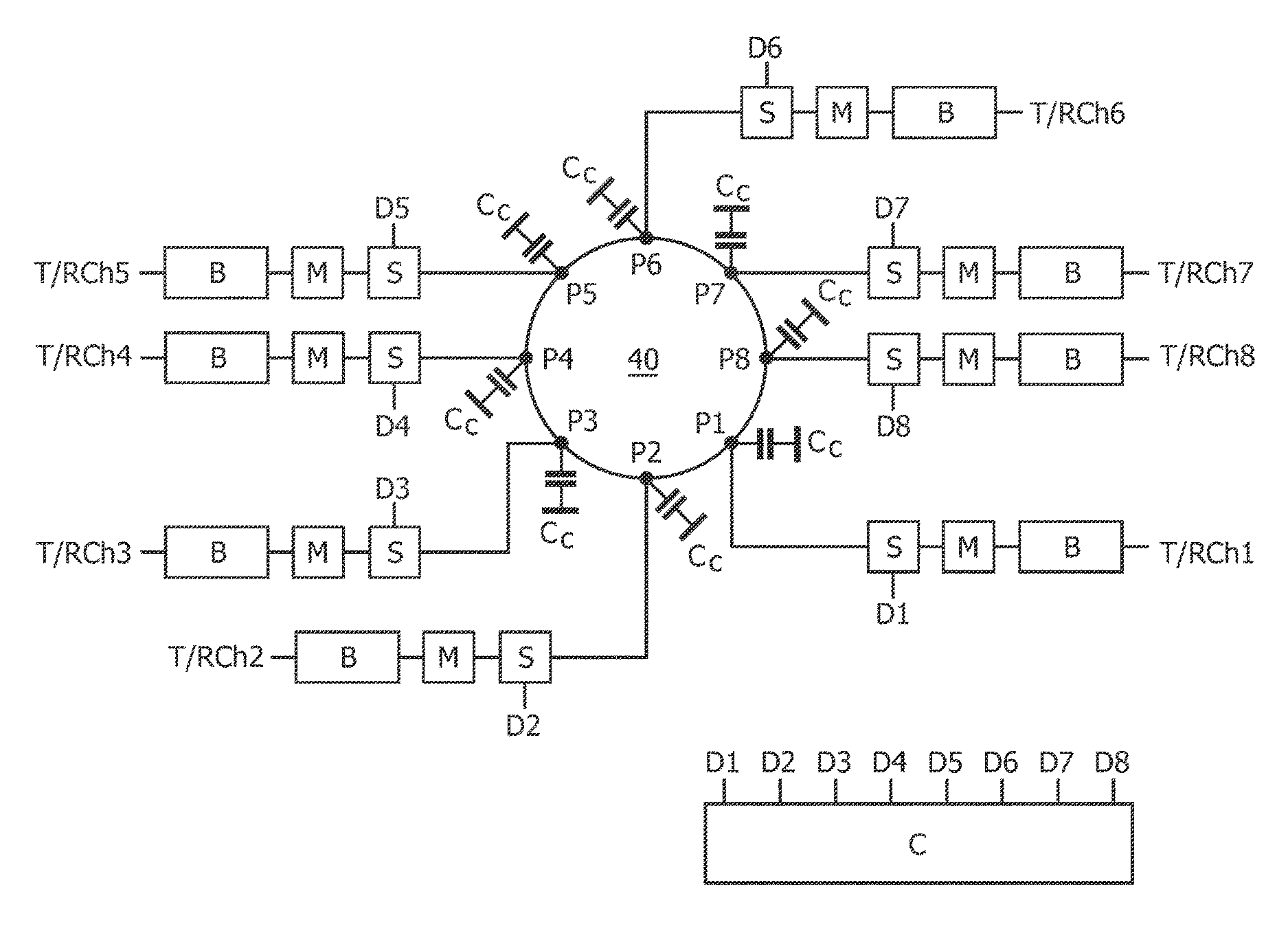
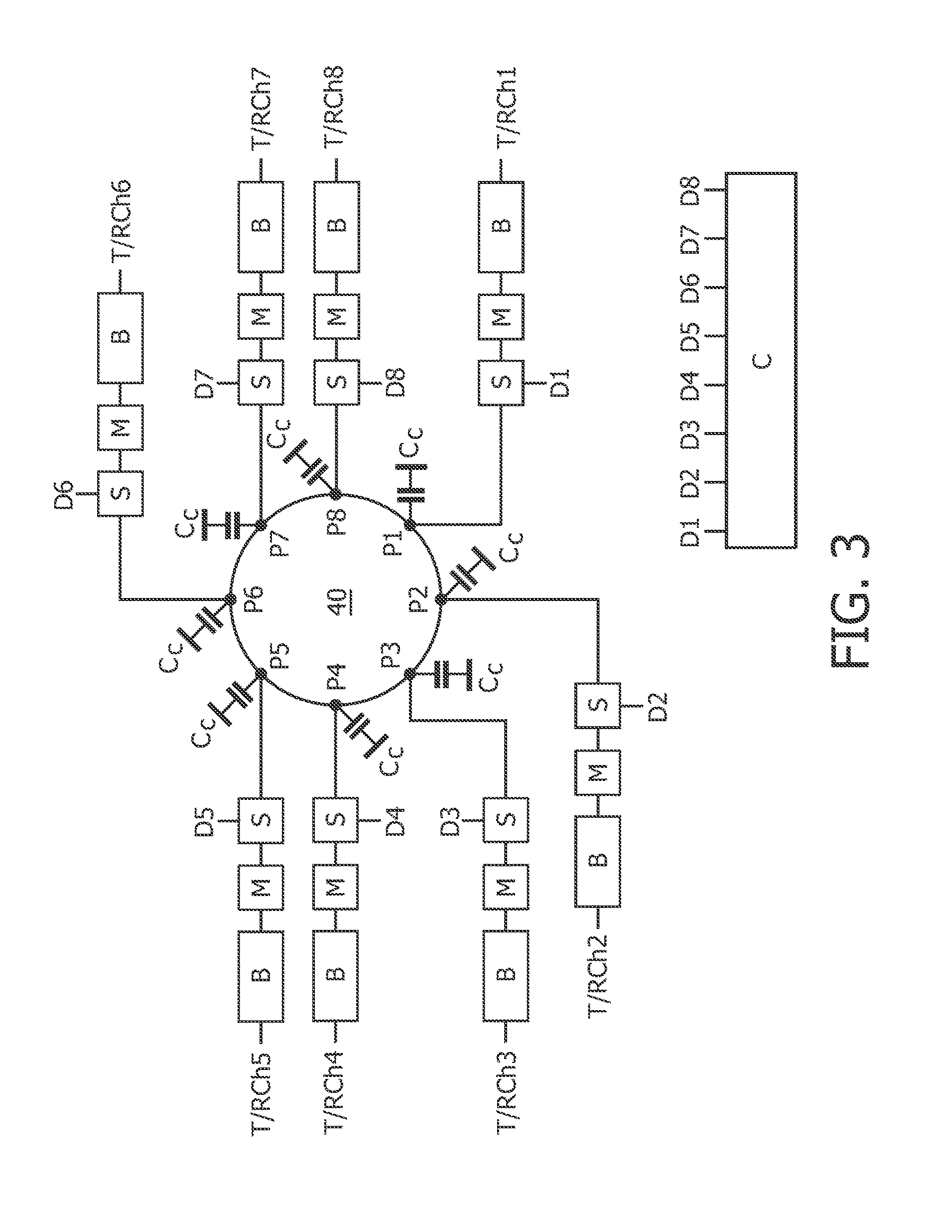
[0052]FIG. 3 schematically shows substantial components of such an RF volume resonator system according to the invention. It comprises a multi-port RF volume resonator preferably comprising a first and a second planar multi-port RF antenna 40, 50 each in the form of a planar electrically conductive plate (only the first planar RF antenna 40 is shown) with a plurality of ports P1, . . . Pn with which each a transmit or receive channel T / RCh is connected.

[0053]The first (and the second) planar multi-port RF antenna 40 is / are preferably provided in the form of each a circular plate which is connected via capacitors Cc to a ground potential in a known manner. The plate can also have an oval or a polyangular or another shape. Along the circumference of the plate, the ports P1, . . . P8 are located, wherein in case of the embodiment shown in FIG. 3 adjacent ports have the same distances in the circumferential direction from each other. However, as mentioned above, these distances can also...

fourth embodiment

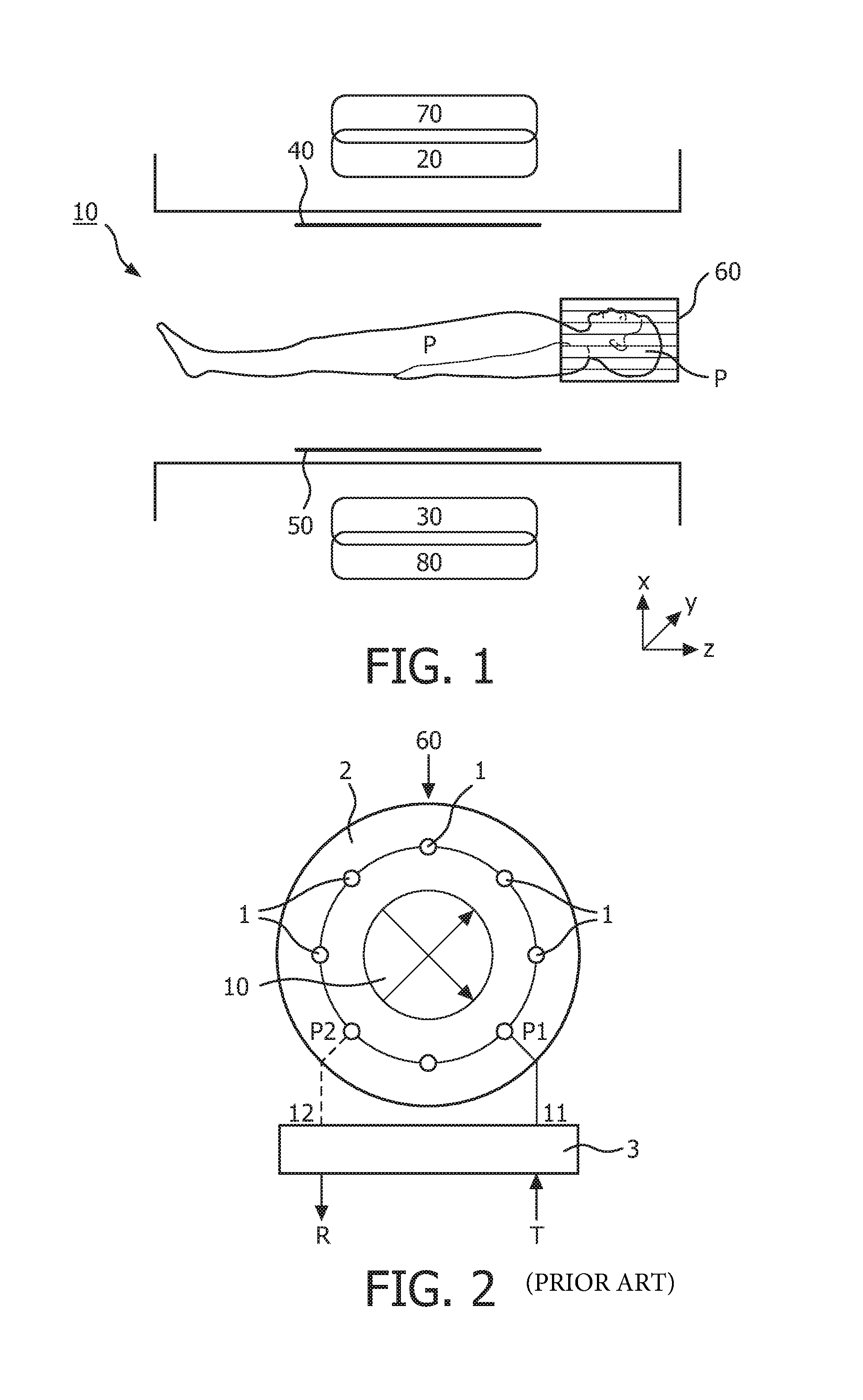
[0072]FIG. 6 shows a schematic three-dimensional view of an RF volume resonator system, again comprising a multi-port birdcage coil 60, which has an at least substantially circular cross section. Further, additionally to the ports P1, P3, P4 and Pn which are arranged at and along the first end conductor 2, one port P2 is exemplarily indicated at one of the rungs 1 of the birdcage coil.

[0073]In contrary to the embodiments shown in FIGS. 3 and 4, the third and fourth embodiment of the RF volume resonator system according to FIGS. 5 and 6, respectively, is provided with transmit and receive channels at each port P1, . . . Pn. For connecting each port either with a power amplifier for transmitting RF signals or with a low noise amplifier for processing received MR signals, each a transmit / receive switch T / R is provided which is connected exemplarily between the matching circuit M and the related amplifiers. However, also the embodiments shown in FIGS. 3 and 4 can be provided with such t...

fifth embodiment

[0076]FIG. 7 shows an RF volume resonator system. Substantially, only the differences to the above embodiments shall be explained.

[0077]This RF resonator system comprises a multi-port RF resonator according to the invention in the form of a birdcage coil which instead of the rungs as indicated in FIGS. 5 and 6 is provided with strip lines 1 as defined above. FIG. 7 shows a part of a related conductor structure 60 schematically unrolled into the two dimensional plane.

[0078]Further, FIG. 7 schematically indicates the first and the second end conductor 2, 3 between which the strip lines 1 extend. The strip lines 1 are coupled at both their ends by means of coupling capacitors CR to the first and the second end conductor 2, 3, respectively. Further, the end conductors 2, 3 comprise capacitors CT which are serially connected into the end conductors 2, 3 for tuning the spectrum of the resonant modes of the RF coil as generally known.

[0079]Preferably at one of the ends of each strip line 1...


PUM


Abstract

An RF volume resonator system is disclosed comprising a multi-port RF volume resonator (40, 50; 60), like e.g. a TEM volume coil or TEM resonator, or a birdcage coil, all of those especially in the form of a local coil like a head coil, or a whole body coil, and a plurality of transmit and / or receive channels (T / RCh1, . . . T / RCh8) for operating the multi-port RF volume resonator for transmitting RF excitation signals and / or for receiving MR relaxation signals into / from an examination object or a part thereof. By the individual selection of each port (P1, . . . P8) and the appropriate amplitude and / or frequency and / or phase and / or pulse shapes of the RF transmit signals according to the physical properties of an examination object, a resonant RF mode within the examination object with an improved homogeneity can be excited by the RF resonator.

Description

CROSS-REFERENCE TO PRIOR APPLICATIONS[0001]This application is the U.S. National Phase application under 35 U.S.C. §371 of International Application No. PCT / IB2012 / 051815, filed on Apr. 13, 2012, which claims the benefit of European Patent Application No. 11163484.6, filed on Apr. 21, 2011 and U.S. Provisional Patent Application No. 61 / 531,157, filed Sep. 6, 2011. These applications are hereby incorporated by reference herein.FIELD OF THE INVENTION[0002]The invention relates to an RF volume resonator system comprising a multi-port RF volume resonator, like e.g. a TEM volume resonator, or a birdcage coil, or a slot-line or other coupled delay structure, all of those especially in the form of a local coil like a head coil, or a whole body coil, and a plurality of transmit channels and / or receive channels for operating the multi-port RF volume resonator for transmitting RF excitation signals and / or for receiving MR relaxation signals into / from an examination object or a part thereof, r...

Claims


Application Information

Patent Timeline
Patent Type & Authority Patents(United States)
IPC IPC(8): G01V3/00G01R33/3415G01R33/36G01R33/561G01R33/34
CPCG01R33/34092G01R33/3415G01R33/3664G01R33/5612
Inventor LEUSSLER, CHRISTOPHFINDEKLEE, CHRISTIANMENS, WILHELMUS REINERIUS MARIA
Owner KONINKLIJKE PHILIPS ELECTRONICS NV
Learn More