Bed frame connector

a technology for connecting rods and bed frames, applied in the field of bed frames, can solve the problems of increasing manufacturing costs, and achieve the effects of reducing the thickness of the connector, improving the effect of securely supporting, and saving material costs

Active Publication Date: 2017-01-10
GRANTEC (XIAMEN) CO LTD
View PDF1 Cites 10 Cited by
  • Summary
  • Abstract
  • Description
  • Claims
  • Application Information

AI Technical Summary

Benefits of technology

[0005]An object of the present invention is to provide a bed frame connector, which has a simple structure and a reduced manufacturing cost and provides advantages of secure support and smooth folding.
[0013]With such a structure, when the bed frame is in an expanded condition, the bed frame connector connects and supports the two lateral bars and the support blocks are exactly located between the two lateral bars to provide support against forces applied to the lateral bars thereby providing a support to a weight placed on the bed frame, making the bed frame supported in a more stable manner and also helping reduce the thickness of the connector. In the present invention, the connector is structured to comprise two support blocks, also for improving the effect of securely supporting and at the same time, saving material cost. When the bed frame is folded, through the connector pivotally connected between the two lateral bars and one end of the connector forming an angled section that is coupled to a side surface of the lateral bars, folding and collecting conducted between the lateral bars can be made more smooth and the bars, after folding, are put close to each other and concentrated, making storage easy.

Problems solved by technology

In such a structure of the connector 3′, the projection flange 33′ requires a large amount of material for formation and this increases the manufacturing cost.

Method used


Image

  • Bed frame connector
  • Bed frame connector
  • Bed frame connector

Examples


Embodiment Construction

[0023]The following descriptions are exemplary embodiments only, and are not intended to limit the scope, applicability or configuration of the invention in any way. Rather, the following description provides a convenient illustration for implementing exemplary embodiments of the invention. Various changes to the described embodiments may be made in the function and arrangement of the elements described without departing from the scope of the invention as set forth in the appended claims.

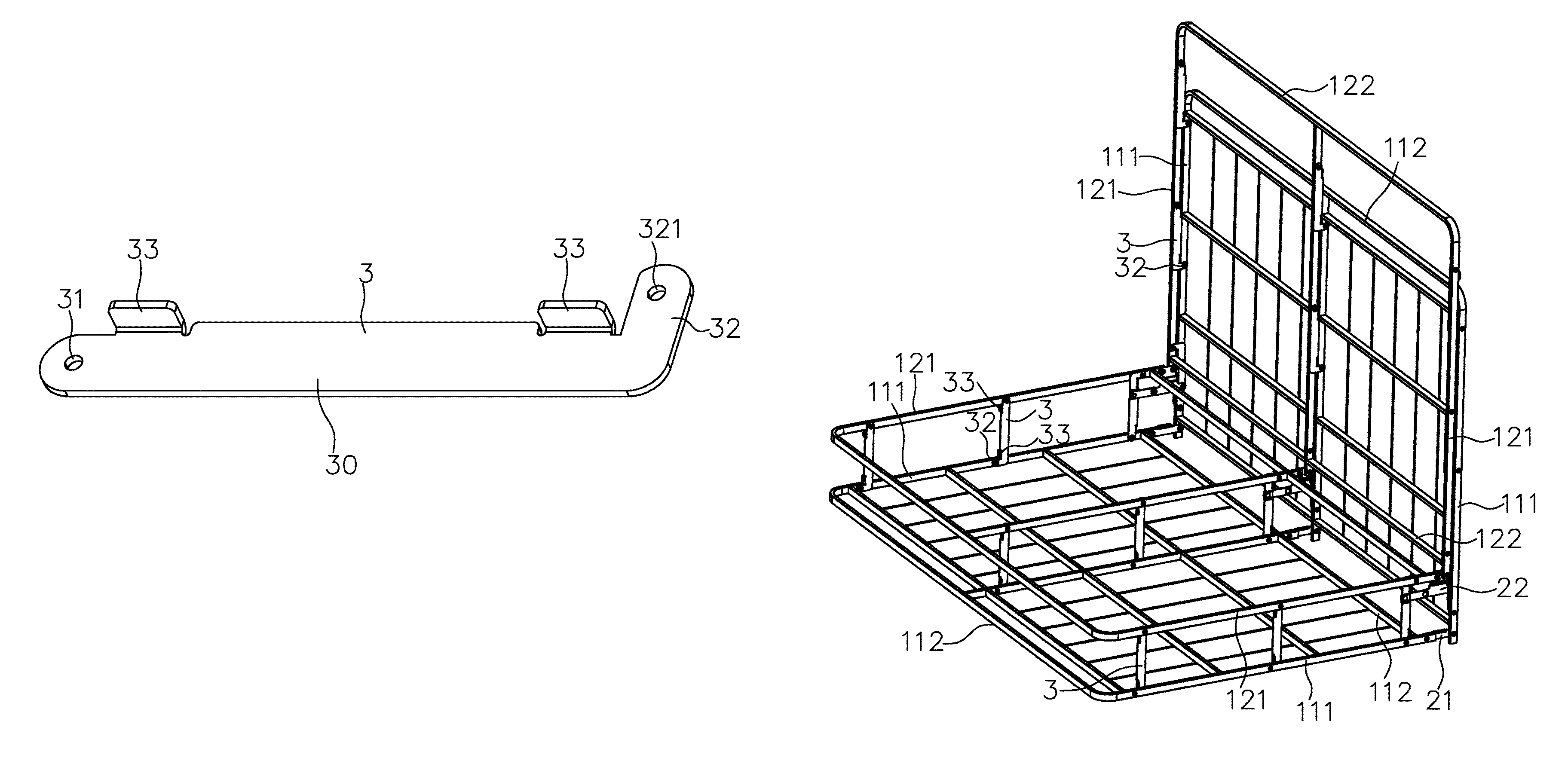
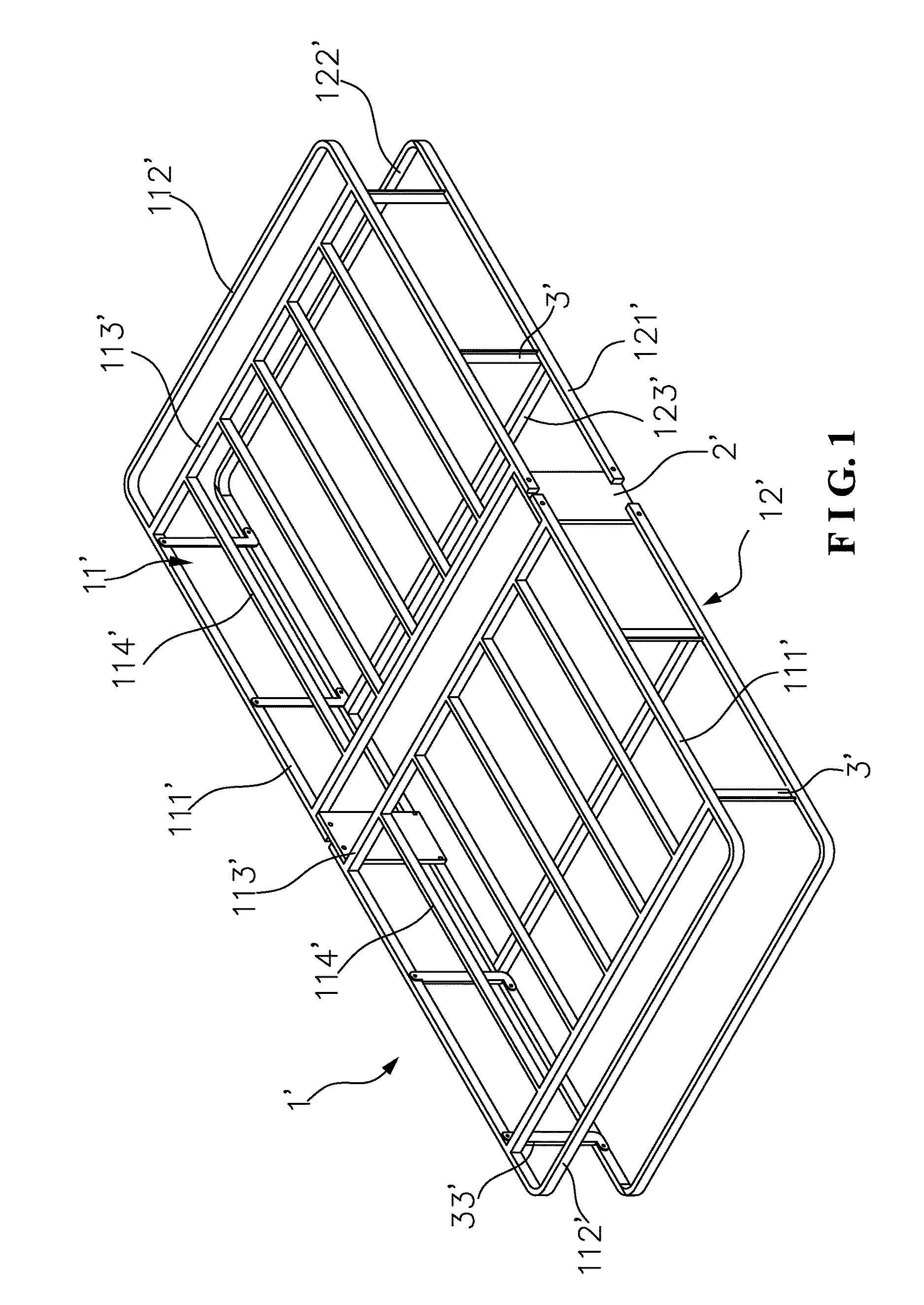
[0024]As shown in FIG. 5, a foldable bed frame comprises a left-side and a right-side basic bed frame assemblies 1. The two basic bed frame assemblies 1 are pivotally jointed at the middle of the bed frame. Each of the basic bed frame assemblies 1 comprises an upper frame sub-assembly 11 and a lower frame sub-assembly 12. The upper frame sub-assembly 11 comprises two lateral bars 111 and two longitudinal bars 112 connected between the two lateral bars 111. Also included are a plurality of longitudin...


PUM


Abstract

A bed frame connector is connectable between upper and lower lateral bars of a foldable bed frame. The bed frame connector includes an L-shaped plate structure that includes a straight body and an angled section extending outward from an end of the straight body. A pivot hole is formed in an end of the straight body and the angled section. The straight body includes two support blocks that project from an edge thereof intersecting the angled section. The two support blocks are positionable between and respectively abutting the upper and lower lateral bars. The present invention has a simple structure and a reduced manufacturing cost and provides secure support and smooth foldability.

Description

TECHNICAL FIELD OF THE INVENTION[0001]The present invention relates generally to a bed frame, and more particularly to a bed frame connector.DESCRIPTION OF THE PRIOR ART[0002]In a bed frame, particularly a foldable bed frame, connectors are mounted to provide necessary supporting. FIG. 1 shows a foldable bed frame, which comprises a basic bed frame assembly 1′ comprising an upper frame sub-assembly 11′ and a lower frame sub-assembly 12′. The upper frame sub-assembly 11′ comprises two lateral bars 111′ pivotally connected to a connection unit 2′ and two longitudinal bars 112′ connected between the two lateral bars 111′. Two longitudinal beams 113′ are arranged between the two lateral bars 111′ and a plurality of lateral beams 114′ is arranged between the two longitudinal bars 112′ to improve the supporting force that the upper frame sub-assembly 11′ supports a mattress or a bed board positioned thereon. The lower frame sub-assembly 12′ has two lateral bars 121′ that are also pivotall...

Claims


Application Information

Patent Timeline
Patent Type & Authority Patents(United States)
IPC IPC(8): A47C19/02F16B12/56
CPCA47C19/02F16B12/56A47C19/122
Inventor OH, SUK KAN
Owner GRANTEC (XIAMEN) CO LTD
Why Eureka
Try Eureka