Method for customizing and manufacturing a composite helmet liner

a composite and helmet technology, applied in the field of helmet structure manufacturing and design, can solve the problems of air gap, increased production cost, and high impact load of the surface area of contact, and achieve the effects of reducing or eliminating air gap, reducing the overall thickness of the protective helmet, and enhancing surface pressure distribution

Inactive Publication Date: 2017-01-17
SANDIFER ALAN T
View PDF14 Cites 32 Cited by
  • Summary
  • Abstract
  • Description
  • Claims
  • Application Information

AI Technical Summary

Benefits of technology

[0011]The helmet comprises a first outer shell fitted with a custom liner, which accurately matches a cranial topography of a user through the use of topographic cranial maps produces by scanned cranial surface data. The custom fit of the liner to the cranium and to the first outer shell results in the reduction or elimination of air gaps within the contact surfaces of the helmet, and provides reduction of an overall thickness of the protective helmet without compromising protection against concussion or traumatic brain injury occurrences. The resultant custom fit also enables enhanced surface pressure distribution to increases helmet stability before, during, and after an impact event.

Problems solved by technology

A persistent problem facing many manufacturers and researchers is developing a helmet that is more conforming to a user's head so as to substantially attenuate, or even obviate, secondary impact without adding significant costs to the production of the helmet.
The undesirable characteristics of prior art helmets are a mismatch, leading to the existence of air gaps, between the liner portion of the helmet and the user's cranium shape.
In fact, these air gaps can create a secondary impact between the liner and the cranium, resulting in localized high impact loads of the surface areas of contact.
Some prior art methods of fabricating such helmet designs are elaborate and costly, and rarely result in proper cranium contour and profile matching, which exacerbates the above-fore-mentioned problems.

Method used


Image

  • Method for customizing and manufacturing a composite helmet liner
  • Method for customizing and manufacturing a composite helmet liner
  • Method for customizing and manufacturing a composite helmet liner

Examples


Embodiment Construction

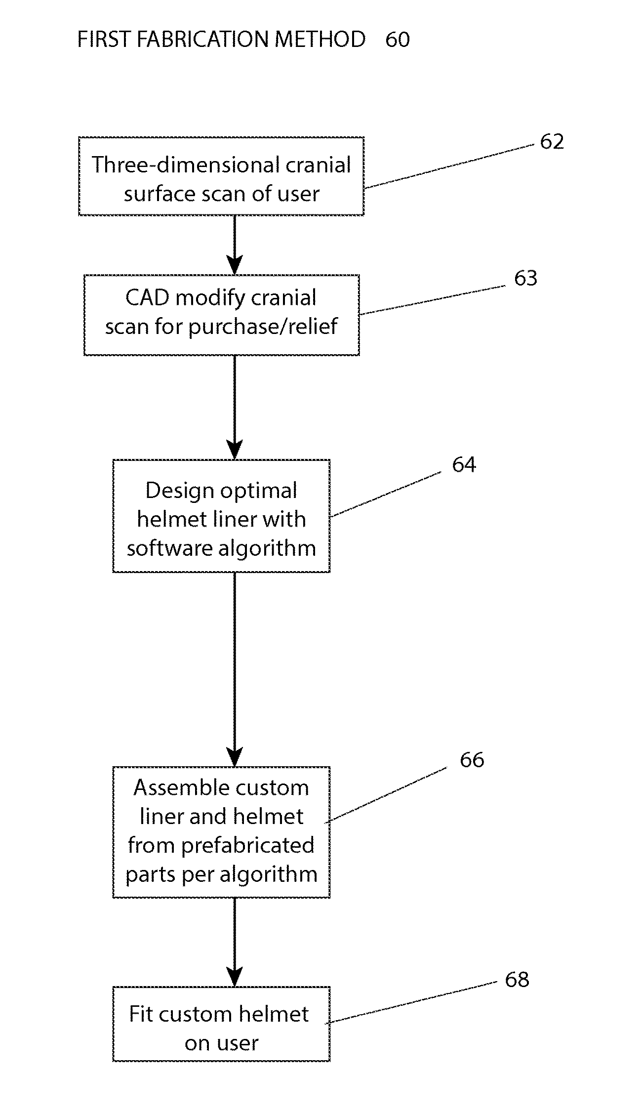
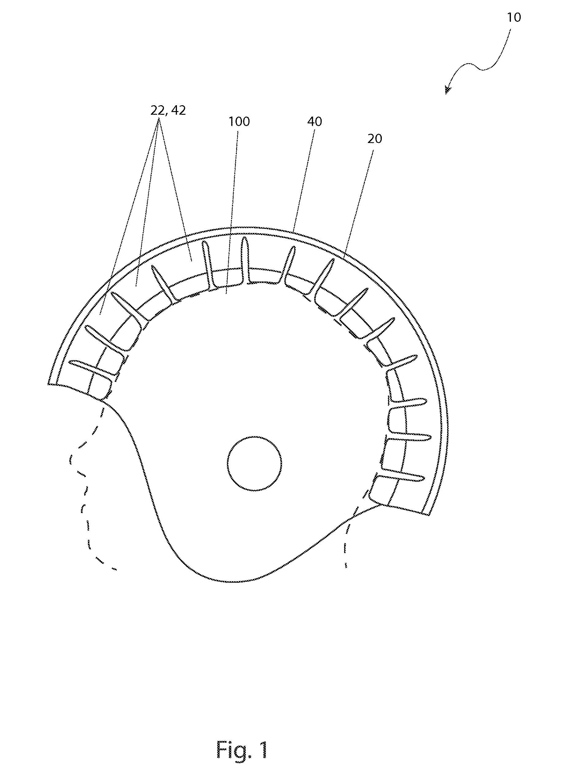
[0067]The best mode for carrying out the invention is presented in terms of its preferred embodiment 10 and fabrication method 60, herein depicted within FIGS. 1 through 6a, and FIG. 7, and in terms of an alternate fabrication method 70, herein depicted within FIG. 6b. However, the invention is not limited to the described embodiment, and a person skilled in the art will appreciate that many other embodiments of the invention are possible without deviating from the basic concept of the invention and that any such work around will also fall under scope of this invention. It is envisioned that other styles and configurations of the present invention can be easily incorporated into the teachings of the present invention, and only one particular configuration shall be shown and described for purposes of clarity and disclosure and not by way of limitation of scope.

[0068]The terms “a” and “an” herein do not denote a limitation of quantity, but rather denote the presence of at least one of...


PUM


Abstract

A method for producing a customized helmet including a computer designed composite helmet liner to be incorporated into existing and new helmet designs is provided by scanning a user's cranial region, creating a computer rendering surface model of the scan, modifying the surface model using computer aided design software, overlaying and aligning an outer helmet shell model onto the modified cranial model to define the custom liner three-dimensional space to configure the composite liner with a software algorithm including shock absorbing segments having optimal sizes, shapes, and materials, fabricating the liner in a heat sealing process to include an optional encapsulating or serial air bladder, and assembling the liner and outer helmet shell together.

Description

RELATED APPLICATIONS[0001]The present invention was first described in and claims the benefit of U.S. Provisional Application No. 61 / 854,012, filed Apr. 15, 2013, the entire disclosures of which are incorporated herein by reference.FIELD OF THE INVENTION[0002]The present invention relates to a method of manufacture and design of a helmet structure to enable customization, reduced bulk, improved protection, and ease of fabrication.BACKGROUND OF THE INVENTION[0003]There are many sports that require the use of helmets such as football, baseball, bicycle riding, hockey, motor sports, and the like. All of these helmets differ in their overall appearance and function, but share the common goal of protecting the user's head from impact. Different areas of coverage, padding, internal suspension, and even the materials used all share the common goal of providing impact protection. These same protective properties are also important in helmets used in medical, construction, military, and law ...

Claims


Application Information

Patent Timeline
Patent Type & Authority Patents(United States)
IPC IPC(8): A42B3/06A42B3/12
CPCA42B3/121A42C2/007
Inventor SANDIFER, ALAN T.
Owner SANDIFER ALAN T
Why Eureka
Try Eureka