

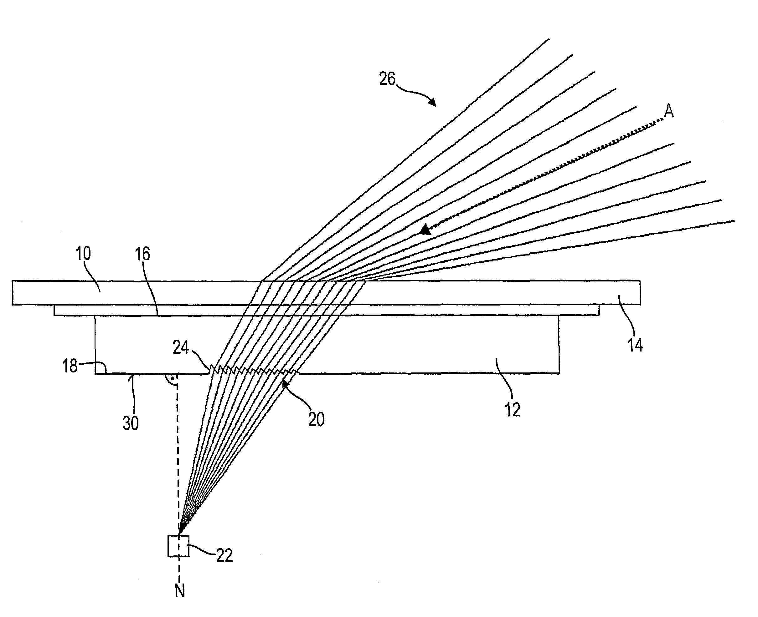
Optical sensing device for detecting ambient light in motor vehicles comprising a prism structure having a plurality of prisms designed to direct rays of a specific ambient light beam
a technology of ambient light and optical sensing device, which is applied in the direction of optical radiation measurement, vehicle cleaning, instruments, etc., can solve the problems of affecting the optical path with traditional lenses, requiring a comparatively large amount of installation space, and substantially reducing the useful light efficiency. , the effect of reducing the sensitivity of interfering ligh
- Summary
- Abstract
- Description
- Claims
- Application Information
AI Technical Summary
Benefits of technology
Problems solved by technology
Method used
Image

Examples
first embodiment
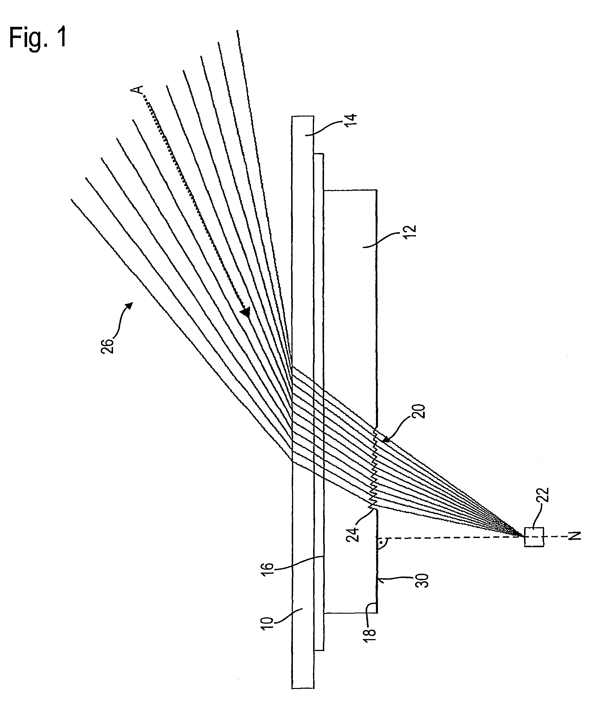
[0031]FIG. 2 shows the prism structure 20, in which rows 28 of single prisms 24 are arranged along parallel straight lines. Such a structure may be referred to as linear prism structure.
second embodiment
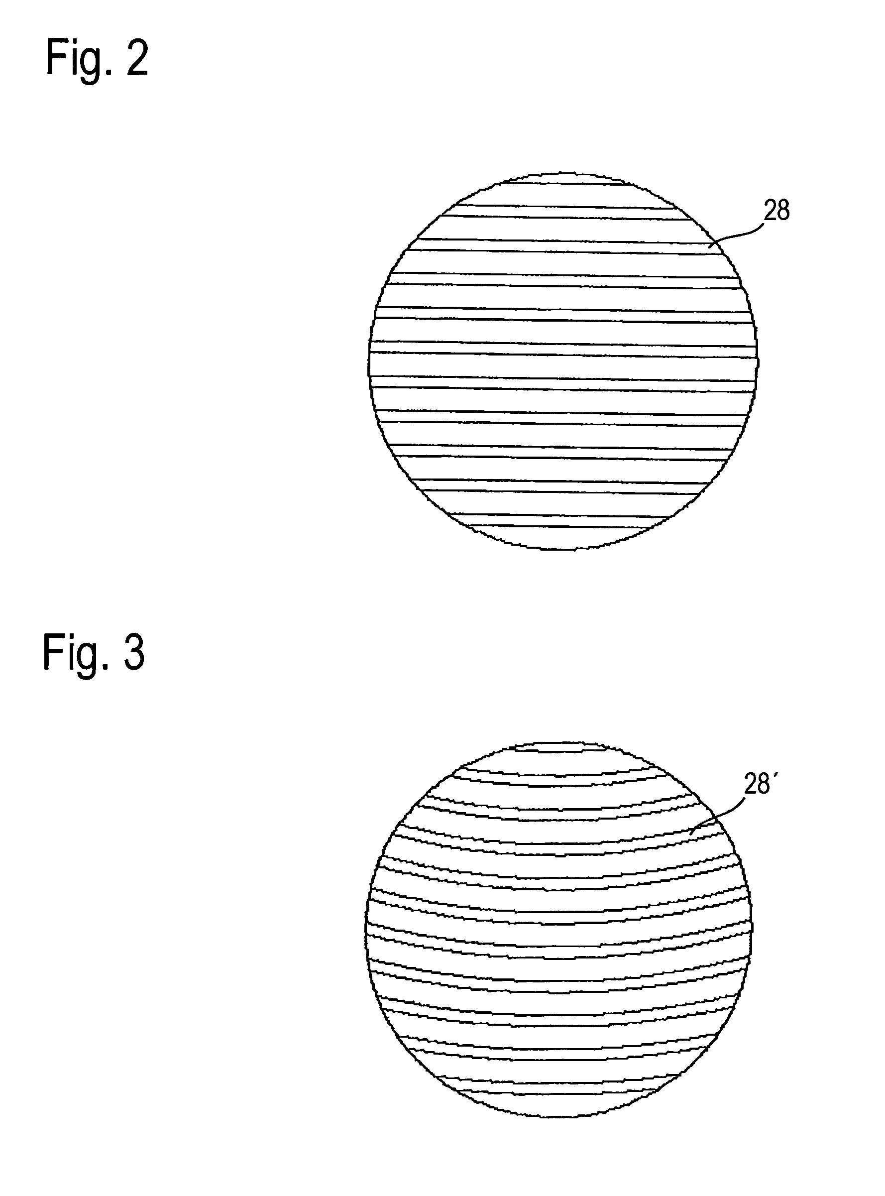
[0032]FIG. 3 shows the prism structure 20, in which rows 28′ of single prisms 24 are arranged along parallel curves, in particular along concentric circular lines, the radii determining the horizontal aperture angle of the detectable ambient light beam 26. Such a structure may be referred to as rotatory prism structure.
[0033]The lens plate 12 of the optical sensor device may also include two prism structures 20 on the second surface 18, e.g. one linear one and one rotatory one. The single prisms 24 of the two prism structures 20 are then designed such that they direct the rays of two ambient light beams 26 having different principal directions A onto the light receiver 22. The two prism structures 20 may also be integrated in each other (superposed).
[0034]Arranged around the prism structure 20 on the second surface 18 of the lens plate 12 is a light lock 30 that is opaque to ambient light. In the exemplary embodiment illustrated in FIG. 1, the entire second surface 18, with the exce...
PUM
 Abstract
Description
Claims
Application Information