Magnetic field generator for a magnetocaloric thermal device, and magnetocaloric thermal device equipped with such a generator

a magnetocaloric thermal and generator technology, applied in the direction of sustainable buildings, energy-efficient heating/cooling, magnetic materials, etc., can solve the problems of reduced cost price, limited useful calorific output, and no magnetic field generator with a small size, etc., to achieve simple geometrical shapes, easy to manufacture, and easy to assemble

Active Publication Date: 2017-01-17
FRANCE BREVETS SAS
View PDF10 Cites 39 Cited by
  • Summary
  • Abstract
  • Description
  • Claims
  • Application Information

AI Technical Summary

Benefits of technology

[0008]The present invention aims to meet these requirements by proposing a magnetic field generator intended to be integrated in a magnetocaloric thermal appliance. This magnetic field generator can create an intense and uniform magnetic field in at least two air gaps. Moreover, the magnetic field generator according to the invention is also easy to manufacture, easy to assemble and includes components with simple geometrical shapes and therefore with low production costs.

Problems solved by technology

Its limits in terms of its useful calorific output and its thermal performance are also well known.
However, there is today no magnetic field generator with a small size, a reduced cost price, that can be mounted in a rotary thermal appliance and is liable to generate an intense and uniform magnetic field concentrated to about one Tesla in at least two air gaps.

Method used


Image

  • Magnetic field generator for a magnetocaloric thermal device, and magnetocaloric thermal device equipped with such a generator
  • Magnetic field generator for a magnetocaloric thermal device, and magnetocaloric thermal device equipped with such a generator
  • Magnetic field generator for a magnetocaloric thermal device, and magnetocaloric thermal device equipped with such a generator

Examples


Embodiment Construction

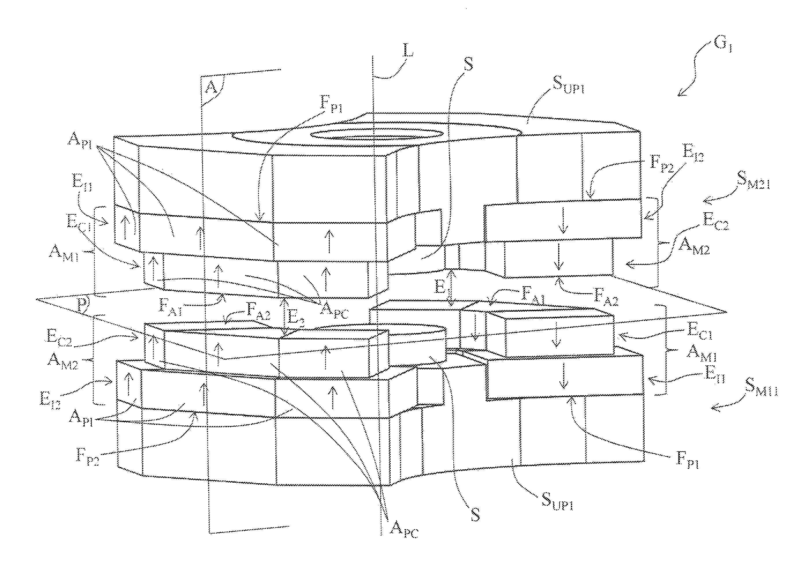
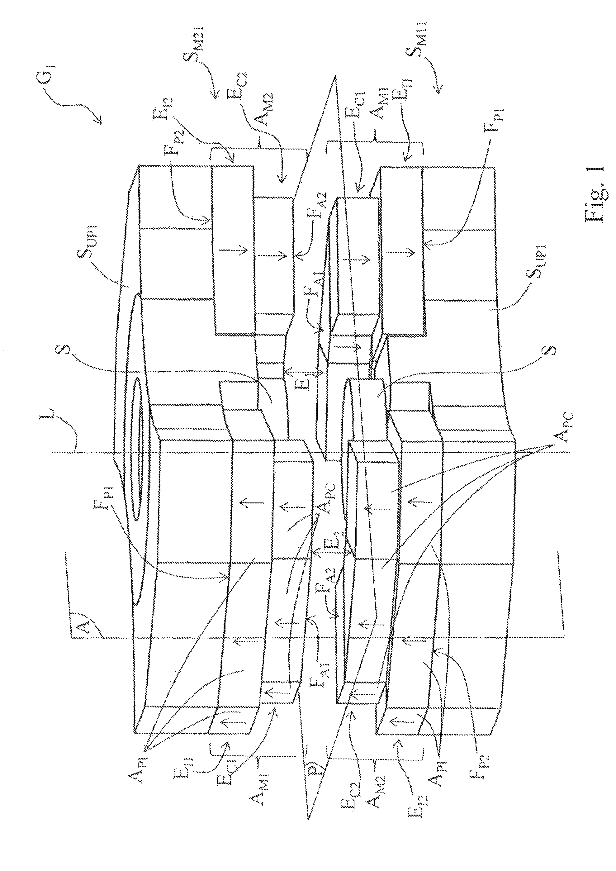
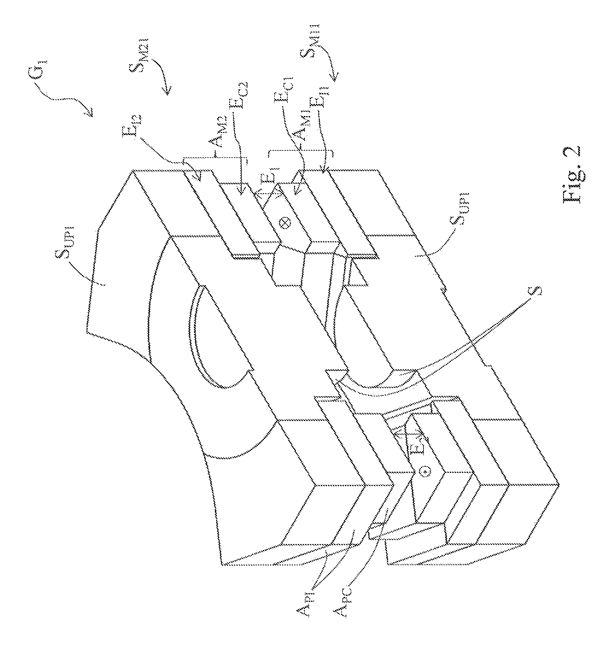
[0048]In the illustrated embodiment examples, the identical pieces or parts have the same numerical references.

[0049]FIGS. 1 and 2 represent a first embodiment of a magnetic field generator G1 according to the invention. This magnetic field generator G1 comprises a first magnetizing structure SM11 and a second magnetizing structure SM21 which are identical, mounted head-to-tail and arranged opposite to each other parallel to a central plane P. They delimit between them two air gaps E1, E2, diametrically opposed with respect to the longitudinal axis L of the magnetic field generator G1. Each magnetizing structure SM11, SM21 comprises a first magnetizing assembly AM1 and a second magnetizing assembly AM2. The two magnetizing structures SM11, SM21 are located with respect to each other so that the first magnetizing assembly AM1 of the first magnetizing structure SM11 is located in front of the second magnetizing assembly AM2 of the second magnetizing structure SM21 and that the second ...


PUM

PropertyMeasurementUnit
magnetic fieldaaaaaaaaaa
magnetic remanenceaaaaaaaaaa

Abstract

A magnetic field generator (G1) for a magnetocaloric thermal device which comprises first (SM11) and second (SM21) identical magnetizing structures mounted head-to-tail, on either side of a central plane (P) and defining two air gaps (E1, E2). Each magnetizing structure (SMM11, SM12) comprises first (AM1) and second (AM2) magnetizing assemblies, whose induction vectors are oriented in opposite directions, and mounted on a support (SUP1). Each magnetizing assembly (AM1, AM2) has a permanent magnet structure (API, APC) which comprises a passive side (FP1, FP2) and an active side (FA1, FA2), delimiting the air gaps (E1, E2). The induction vectors of the first (AM1, AM19) and the second (AM2, AM29) magnetizing assemblies, form inside the generator, a single circulation loop of a magnetic field through the supports (SUP1) and the air gaps (E1, E2, E3, E4).

Description

[0001]This application is a National Stage completion of PCT / IB2013 / 001628 filed Jul. 26, 2013, which claims priority from French patent application serial no. 12 / 57323 filed Jul. 27, 2012.FIELD OF THE INVENTION[0002]The present invention relates to a magnetic field generator for a magnetocaloric thermal device with a rotary structure, said magnetic field generator comprising a first and a second identical magnetizing structures mounted head-to-tail, opposite to each other, parallel on either side of a central plane and arranged to define at least two air gaps located in a same plane and diametrically opposed, each magnetizing structure comprising a first and a second structurally identical magnetizing assemblies, diametrically opposed, mounted on a support made out of at least one ferromagnetic material and delimiting said at least two air gaps.[0003]It also relates to a magnetocaloric thermal device with a rotary structure, provided with at least one disk comprising magnetocaloric...

Claims


Application Information

Patent Timeline
Patent Type & Authority Patents(United States)
IPC IPC(8): F25B21/00H01F7/02H01F1/01
CPCH01F7/0273F25B21/00H01F1/012F25B2321/0022Y02B30/66Y02B30/00
Inventor MULLER, CHRISTIAN
Owner FRANCE BREVETS SAS
Why Eureka
Try Eureka