Balancing and control valves

a technology of control valves and balancing valves, applied in the direction of valve operating means/releasing devices, functional valve types, service pipe systems, etc., can solve the problems of unsatisfactory fluid conductance, inability to control, and excessive pumping energy required to address unnecessary pressure, so as to reduce noise, reduce turbulence, and facilitate fluid conductance change

Inactive Publication Date: 2017-01-24
TA HYDRONICS SA
View PDF24 Cites 1 Cited by
  • Summary
  • Abstract
  • Description
  • Claims
  • Application Information

AI Technical Summary

Benefits of technology

[0011]The adjustment needed for the balancing of circuits is accomplished by limiting the maximum opening of the control valve by use of a calibrated scale which provided a known restriction at any particular setting. The flow rate reading needed for the balancing of circuits is accomplished by reading the differential pressure across the valve restriction. In one practical embodiment of the invention, the adjustment means includes a calibration means having a scale visible outside of the chamber and is operable to adjust a maximum possible separation of the plug and seat in increments corresponding to units provided on the scale. After the balancing procedure, the actuator can change the conductance of the valve to any appropriate value between closed and the set maximum value in response to an external control signal.
[0014]Desirably the valve and seat are arranged in axial alignment with the intended direction of flow of fluid in the system. In an axial geometry, fluid flows into and out of the valve along a single axis, and the valve has a plug which moves along that same axis. This geometry provides reduced turbulence and consequently less noise than geometries which require the fluid to change direction excessively. This geometry also allows the valve to be more compact than other geometries.
[0016]The geometry of the cam is selected to translate constant motion from an actuator into a favourable motion of the plug, thereby providing a favourable change in the fluid conductance of the valve in response to a control signal. For example, the cam might be so designed that the valve opening compensates for the output characteristic of a heat transfer device, thereby creating a more nearly linear relation between the control signal and the heat transfer. Such a linear relationship between the control signal and the desired controlled variable is sometimes referred to as a constant gain and is advantageous to control systems. The cam motion may also provide a mechanical advantage to an actuator in moving the plug as it nears its closed position, thereby reducing power needed to drive the actuator.
[0017]Preferably the plug and seat are configured to provide a fluid conductance which is approximately proportional to the movement of the plug. Optionally, the plug may be provided with partial differential pressure compensation, further reducing the needed power of the actuator.
[0018]Optionally, axial movement of the shaft is resisted by a biasing spring which might be arranged either to bias the valve in an open position or a closed position. Desirably, the biasing spring urges the valve to open, this assists in preventing oscillations.

Problems solved by technology

If these control valves are chosen with a maximum opening that is larger than the maximum needed for the application, then they must be controlled to close excessively at all times. This excessive closure results in unstable control as the control valve changes from an open to a closed condition repeatedly rather than settling at the proper location.
Conversely, if the valve is chosen with too small a maximum opening, excessive pumping energy is required to address unnecessary pressure drops arising in the system.
This problem is compounded by the fact that control valves are ordinarily available only in fixed steps, forcing the user to select one or another type of error.
An ordinary control valve provides no means for reading the flow rate of the fluid, nor of manually adjusting its maximum opening which will cause an ordinary control valve to flow incorrectly.
While the amount of surplus pressure might be calculated in theory, in practice the calculations are often not done due to their complexity, or are inaccurate due to construction variations.
A limitation of current techniques is that the restriction created by the balancing valve is not taken into account by the control valve, so that a portion of the control valve's stroke is wasted.

Method used


Image

  • Balancing and control valves
  • Balancing and control valves
  • Balancing and control valves

Examples


Embodiment Construction

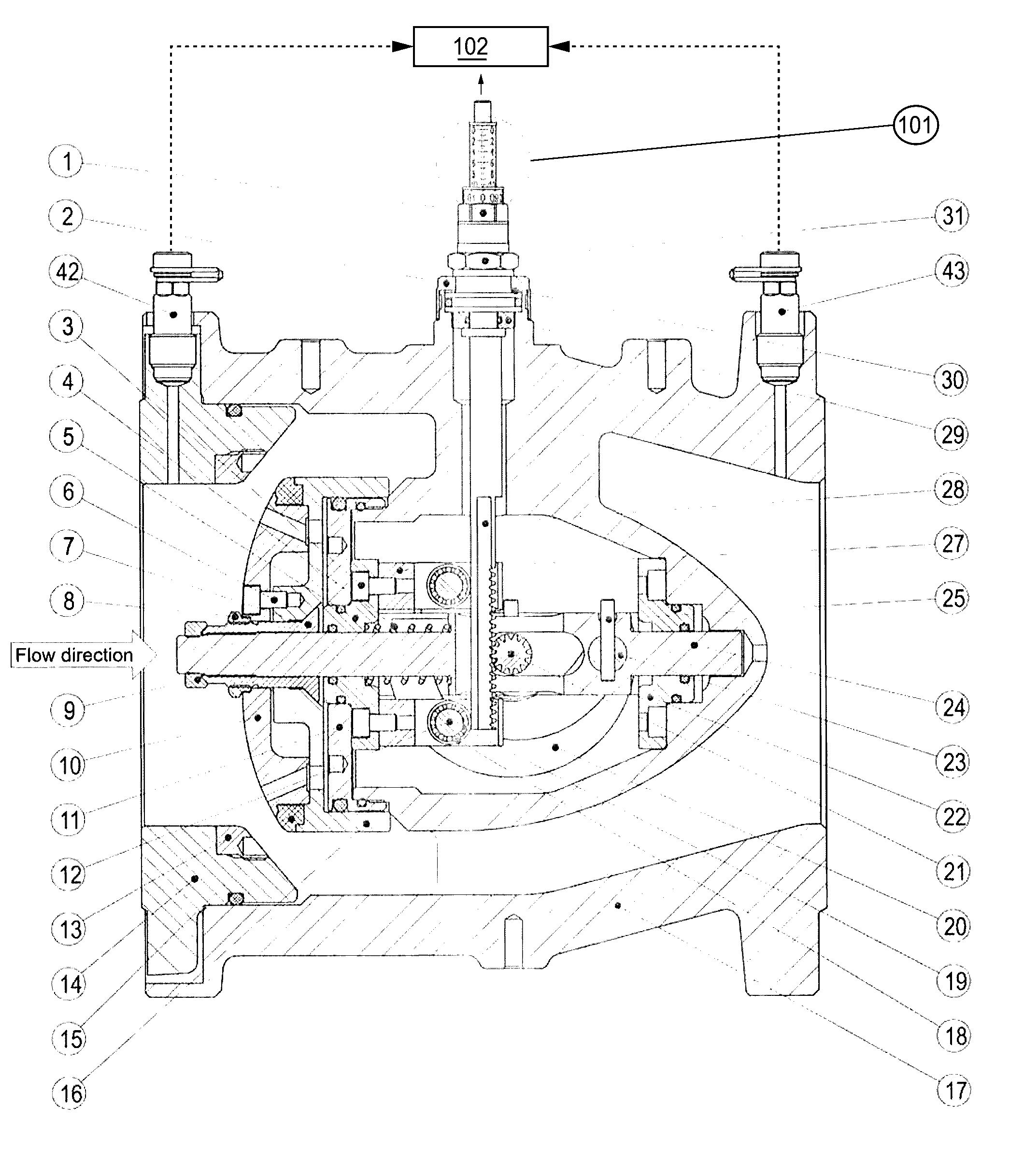
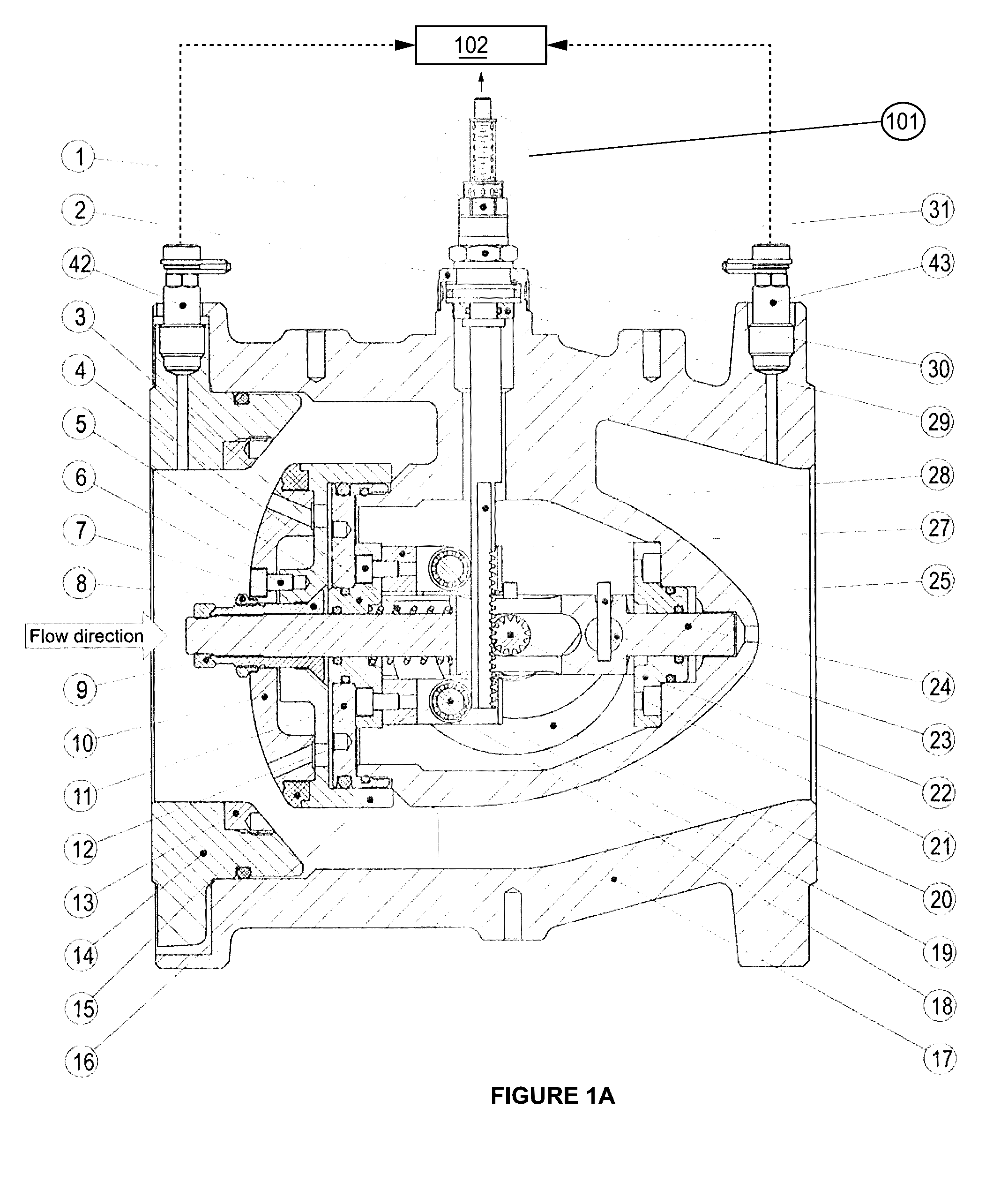
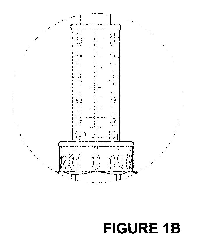
[0027]The valve of FIG. 1A generally comprises a housing (14, 17) which defines a chamber in which is provided a plug assembly (6, 10, 15, 16) and a seat (13) in axial alignment along the direction of flow of fluid in hydronic system. The plug (6, 10, 15, 16) is carried on a shaft (24) whose axis passes through the centre of the plug (6, 10, 15, 16). The shaft (24) also carries a cam follower assembly (23, 25). A calibration means is provided in the form of assembly (1, 2, 29, 30 and 31) which interacts with a rod (28) which passes through a sealed inlet chamber which is free to slide axially by means of a bearing mounted in the inlet. The rod is adapted to connect to an electromechanical or other controlled drive means (45 in FIG. 4). The calibrated stroke limiting mechanism (1, 2, 28, 29, 30, 31) is provided to adjust the maximum opening of the valve during a balancing procedure.

[0028]The rod (28) extends into the chamber in a direction perpendicular to the motion of the plug and ...


PUM


Abstract

A combined balancing and control valve suitable for use in a hydronic system is provided, including a chamber enclosing a plug (6, 10, 16, 15), a seat (13) and a cam and pinion mechanism (20-28) for adjusting the separation of the plug (6, 10, 16, 15) and the seat (13). Pressure ports (42, 43) are included for monitoring the rate of fluid flow across the separation. The cam and pinion mechanism provides a motion transformation (20-27) operable by an actuator (28) to control the motion of the valve plug (6, 10, 16, 15). The valve plug motion provides a favorable change in conductance of the valve for a given change in the actuator position. The actuator (28) is calibrated in increments which correspond to incremental changes in the conductance.

Description

CROSS-REFERENCE TO RELATED APPLICATIONS[0001]This application is a continuation of PCT Application PCT / EP2011 / 006144, filed Dec. 7, 2011, and published under the PCT Articles in English as WO 2012 / 076167 on Jun. 14, 2012. PCT / EP2011 / 006144 claimed priority to European Application No. EP10015371.7, filed Dec. 7, 2010. The entire disclosures of PCT / EP2011 / 006144 and European Application No. EP10015371.7 are incorporated herein by reference in their entirety.BACKGROUND OF THE INVENTION[0002]Field of the Invention[0003]The present invention relates to control valves and balancing valves commonly used in hydronic systems to monitor and adjust fluid flow rate and ensure a relatively steady flow of fluid through the system. The invention provides a control valve incorporating a novel design of balancing mechanism which results in better performance of a hydronic system when the improved valve is incorporated.[0004]Background Art[0005]In fluid networks, it is common to distribute fluid from...

Claims


Application Information

Patent Timeline
Patent Type & Authority Patents(United States)
IPC IPC(8): F16K37/00F16K31/53F16K1/12F16K31/524F16K31/54F16K31/52
CPCF16K37/0016F16K1/12F16K31/52F16K31/52433F16K31/53F16K31/54Y10T137/8275F16K37/00F16K1/126F16K31/524
Inventor VOLOVEC, PETER
Owner TA HYDRONICS SA
Why Eureka
Try Eureka