Supercharge Your Innovation With Domain-Expert AI Agents!

Pulsed UV-light source

a pulsed light source and pulse technology, applied in the field of pulsed light sources, can solve the problems of limiting the lifetime of the crystal, affecting the performance of the light source, and affecting the performance of the light source, and achieve the effect of low cos

Active Publication Date: 2017-01-24
NKT PHOTONICS
View PDF15 Cites 2 Cited by
  • Summary
  • Abstract
  • Description
  • Claims
  • Application Information

AI Technical Summary

Benefits of technology

[0017]In view of the foregoing an object of the present invention is to provide a low cost tunable light source spanning the UV-range and possible also the visible and near-IR wavelengths.
[0023]Surprisingly, the inventors have discovered that it is possible to frequency double SC sources with a relatively simple and inexpensive frequency doubling set-up, and that the output spectral density can be in the order of μW, such as at least 1 μW, which is sufficient to detect the pulses and hence enabling use of such light source for a number of bio-optical measurements.
[0057]As will be clear to the skilled person a similar SC source could be built using either fewer or more amplifiers and isolators. SC sources can also be based on a Q-switch SEED laser, as e.g. the SuperK Compact from NKT Photonics A / S. Inside the non-linear fiber the super continuum spreads in time due to the chromatic dispersion of the non-linear fiber. As the chromatic dispersion is wavelength dependent, different wavelength of light will in general be offset with respect to each other and will leave the non-linear fiber at a different time. Furthermore the pulse duration will vary as a function of the wavelength. As prior described the pulse length of the super continuum source tSC is defined as the shortest pulse length of the SC source when measured over the visible range (400-800 nm). Furthermore tSC will increase with the length of the non-linear fiber. This will decrease the intensity of the light impingent on the non-linear crystal and hence the efficiency of the frequency doubling. Accordingly, in one embodiment of the light source of the invention, the length of the non-linear fiber is less than 10 m, such as less than 5 m, such as less than 2 m, such as less than 1 m, such as less than 0.5 m.
[0068]In one embodiment of the invention the non-linear fiber is tapered along its longitudinal axis to increase the amount of light below 450 nm and / or reduce the noise of the supercontinuum source and / or reduce the length of the non-linear fiber. An example of such a taper can be found in patent application WO2012028152.
[0073]As briefly mentioned, the light source of the present invention comprises advantageously a non-linear crystal optimized for sum frequency mixing. To achieve frequency conversion in such non-linear crystal requires that two beams are impinging on it. The frequency conversion will depend on phase matching between the two incoming beams and the frequency converted beam. An advantage of this approach is that the second beam can have a larger intensity than the SC beam and hence increase the efficiency of the frequency conversion. Preferable this second beam is extracted from the SC source, at a position prior to the non-linear fiber and sent through a delay unit providing a variable delay stage so that it arrives at the non-linear crystal simultaneously with the output from the SC source. Furthermore the two beams might be recombined prior to the non-linear crystal, see FIG. 15. Thus in one embodiment the non-linear crystal is optimized for sum frequency mixing between the output from the SC source and a second output extracted from the SC source prior to that the beam has traversed the non-linear filter. In one embodiment the second output from the SC source is amplified and / or sent through a variable delay stage and / or frequency doubled prior to reaching the non-linear crystal.

Problems solved by technology

However, high intensity light will often lead to degradation of the crystal and hence limit its lifetime.
However, it has a large cost, is complex to operate and requires highly skilled operators, and thus also has a large cost of ownership.

Method used


Image

  • Pulsed UV-light source
  • Pulsed UV-light source
  • Pulsed UV-light source

Examples


Embodiment Construction

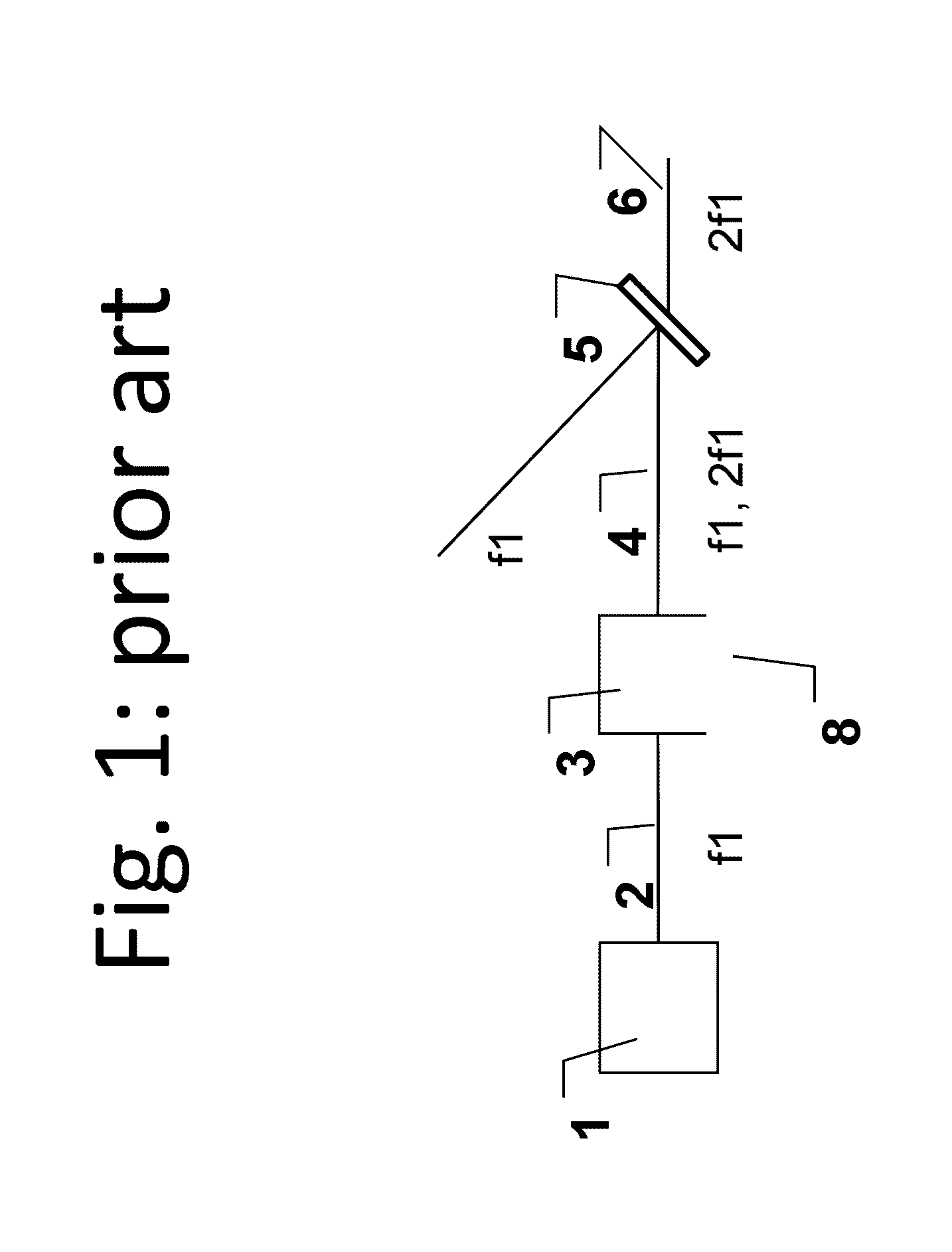
[0080]FIG. 1 shows a schematic frequency doubling unit from prior art.

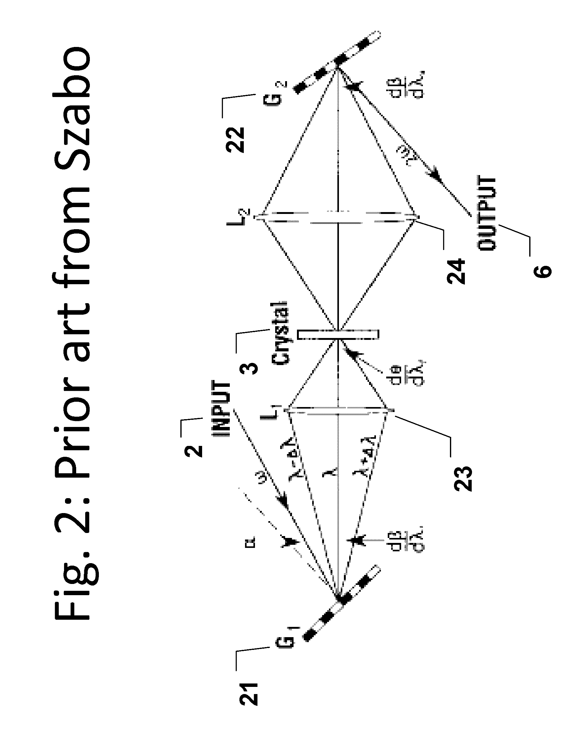
[0081]FIG. 2 shows a prior art demonstration of a broadband frequency doubler for broadband pulses, as published by Szabo.

[0082]FIG. 3 shows a prior art demonstration of a broadband frequency doubler for broadband pulses, as published by Baum.

[0083]FIG. 4 shows a prior art super continuum source.

[0084]FIG. 5 shows a prior art filtering system for a super continuum source.

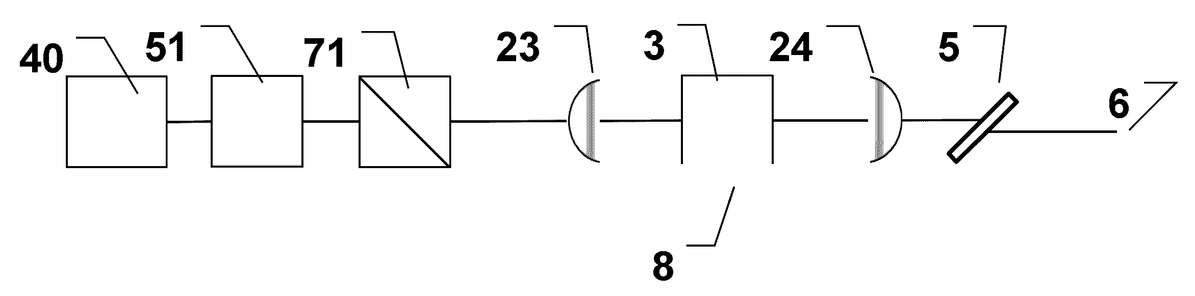
[0085]FIG. 6 shows a tunable pulsed source according to the invention.

[0086]FIG. 7 shows a tunable pulsed source according to the invention. This embodiment is used to generate the experimental data shown in FIGS. 8 to 14.

[0087]FIG. 8 shows the power spectral density of a SC source 80 and after that the spectrum has been filtered in a low pass filter 81.

[0088]FIG. 9 shows the pulse arrival time as a function of wavelength from a SC source. The difference in arrival time between the light at 500 nm and the light at 800 nm is more than 600 ps.

[0089]...


PUM

PropertyMeasurementUnit
output wavelength WUVaaaaaaaaaa
focal lengthaaaaaaaaaa
lengthaaaaaaaaaa

Abstract

The disclosure relates to a tunable optical light source spanning the UV-range and possible also the visible and near-IR wavelengths. The tunable optical light source includes an input light source, a focusing element, a non-linear crystal arranged to convert the frequency of at least part of the output spectrum of the super continuum source, and a holding unit for the non-linear crystal. The input light source is a super continuum light source with a spectral bandwidth of at least about 300 nm and the holding unit is adjustable for changing the frequency converted output wavelength of the non-linear crystal wfc such that the lowest obtainable output wavelength wUV of said tunable light source is ultraviolet. The disclosure further relates to an illumination source and an optical measurement system.

Description

TECHNICAL FIELD[0001]The present invention relates to a tunable pulsed light source spanning the UV range and suitable for use in an illumination source and / or an optical measurement system. The invention also relates to an illumination source as well as an optical measurement system comprising such tunable pulsed light source.BACKGROUND ART[0002]Optical measurement systems are frequently used to analyze biological and chemical substances. In e.g. confocal microscopes a fluorophor is added to the substance under test. A laser light is used to excite the fluorophor, and when it subsequently decays radiatively a camera can detect its position.[0003]Light is also used to study physical, chemical and biological reactions, which typically occur on a femtosecond (fs) to nanosecond (ns) scale. This is conventionally done by having a pump laser and a fs probe laser, which is slightly delayed compared to the pump laser.[0004]In order to analyze many different samples and substances the optic...

Claims


Application Information

Patent Timeline
Patent Type & Authority Patents(United States)
IPC IPC(8): G02F1/35G01N21/25G01N21/00H01S3/09
CPCG01N21/00G01N21/255G02F1/3501G02F2001/3528H01S3/09G02F1/3528
Inventor THOMSEN, CARSTEN L.NIELSEN, FREDERIK DONBAEKHAUSER, SASCHARIEDLE, EBERHARDBRADLER, MAXIMILIAN
Owner NKT PHOTONICS
Features
  • R&D
  • Intellectual Property
  • Life Sciences
  • Materials
  • Tech Scout
  • Unparalleled Data Quality
  • Higher Quality Content
  • 60% Fewer Hallucinations
Learn More