Pressure control valve assembly

a technology of pressure control valve and assembly, which is applied in the field of valves, can solve the problems of reduced service life, reduced process throughput, and reduced service life, so as to improve or precisely position control, the effect of reducing the formation of particulates

Active Publication Date: 2017-02-07
HVA
View PDF9 Cites 0 Cited by
  • Summary
  • Abstract
  • Description
  • Claims
  • Application Information

AI Technical Summary

Benefits of technology

[0007]Various aspects of the present application are directed to provide a pressure control valve assembly that provides easy accessibility for maintenance or other services, does not require recalibration after maintenance or other services, minimizes the particulate formation, and / or has a better or precise position control.

Problems solved by technology

Although current gate valves can provide pressure control in a processing chamber, they may be at a disadvantage in terms of maintenance serviceability, minimal particulate formation, and / or precise positioning of the valve gate.
As a result, the motor and its associated interface need to be recalibrated after the service, causing increased downtime and maintenance cost and lower process throughput.
Another disadvantage relates to the particulate formation.
Because the linkage system and the ball detent mechanism are employed in the current gate valve design, there exist many metal to metal contacts within the valve body, leading to particulate formation and hence risk of contamination in the processing chamber.
In addition, the crank and link system cannot provide a precision control on positioning the valve gate.

Method used


Image

  • Pressure control valve assembly
  • Pressure control valve assembly
  • Pressure control valve assembly

Examples


Embodiment Construction

[0033]Reference will now be made in detail to various embodiments of the present invention(s), examples of which are illustrated in the accompanying drawings and described below. While the invention(s) will be described in conjunction with exemplary embodiments, it will be understood that present description is not intended to limit the invention(s) to those exemplary embodiments. On the contrary, the invention(s) is / are intended to cover not only the exemplary embodiments, but also various alternatives, modifications, equivalents and other embodiments, which may be included within the spirit and scope of the invention as defined by the appended claims.

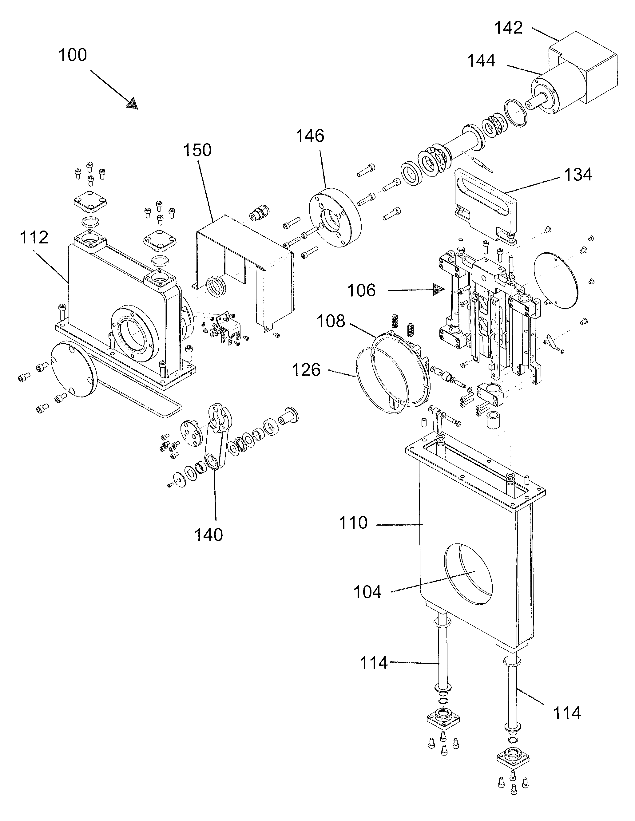
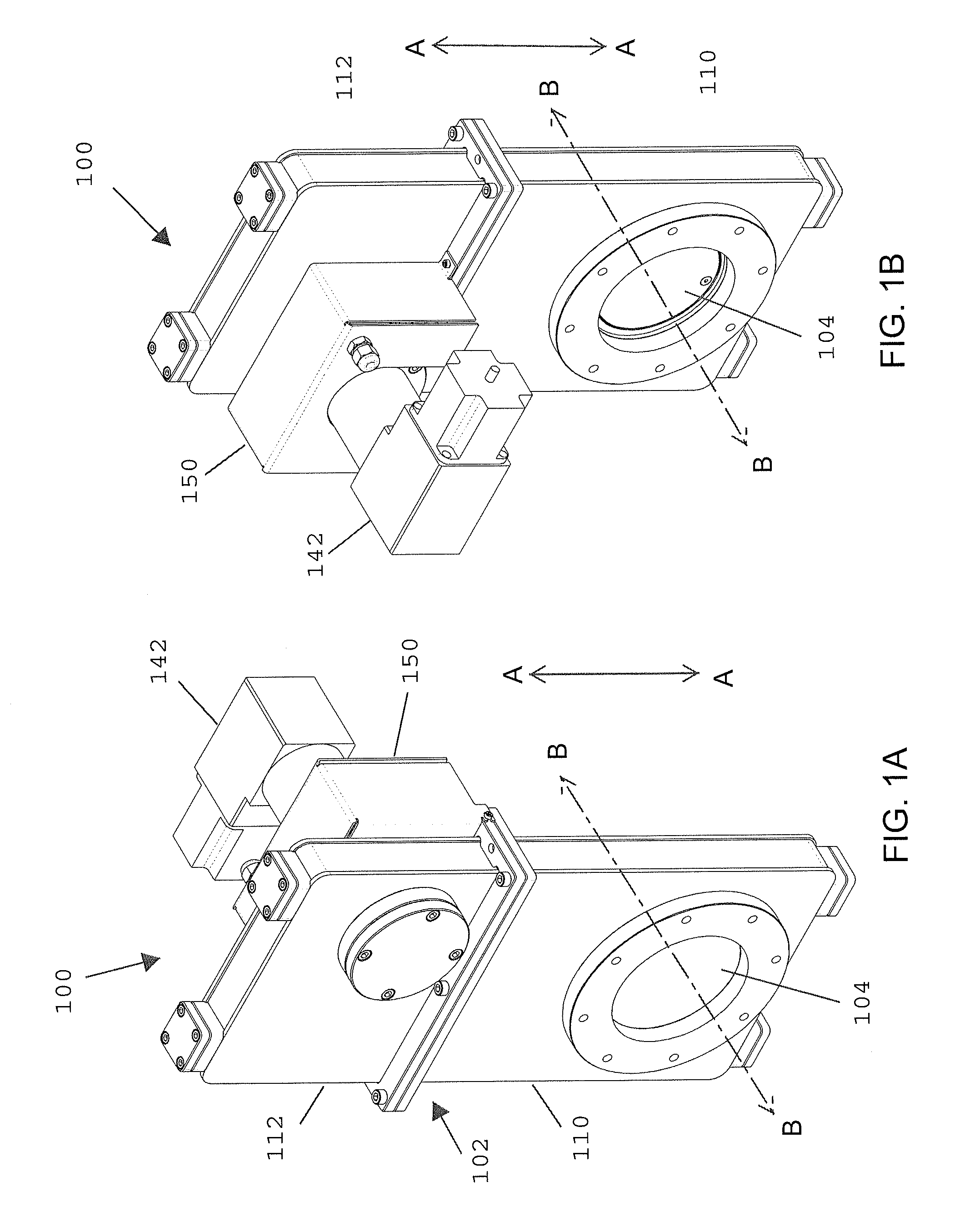
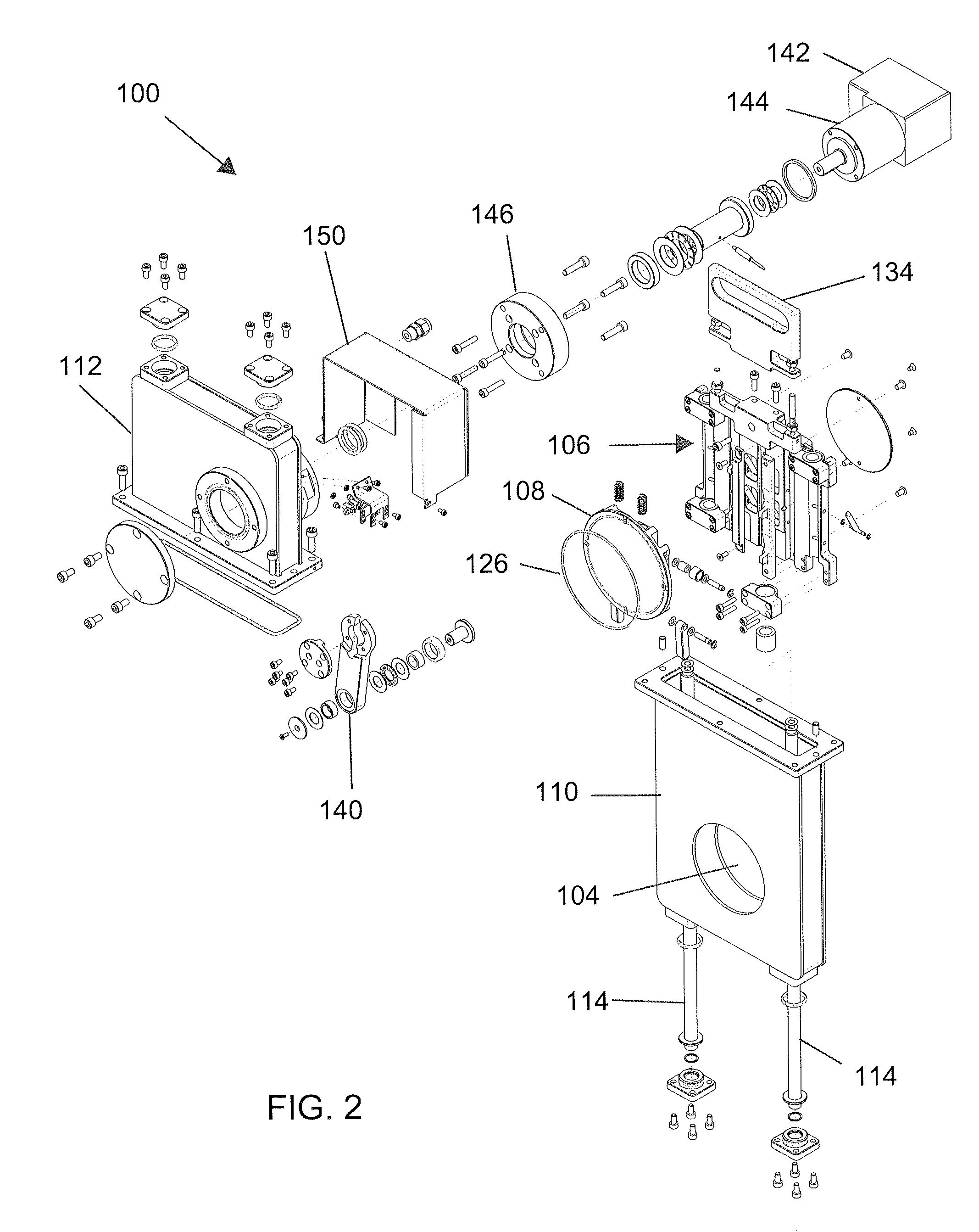
[0034]Referring to FIGS. 1 and 2, there are respectively depicted a fully assembled and a fully disassembled exemplary pressure control valve assembly 100. In various embodiments, the exemplary pressure control valve assembly 100 generally includes a valve housing 102 that is formed with a valve opening 104, a strongback assembly 106 ...


PUM


Abstract

A pressure control valve assembly includes a valve body including a valve opening that is characterized by an axis, a bonnet assembly removably attached to the valve body, wherein the bonnet assembly and the valve body collectively form a valve housing, and the valve housing defines a moving direction that is substantially perpendicular to the axis, a strongback assembly movably disposed in the valve housing and capable of moving in the moving direction defined by the valve housing, and a valve gate movably mounted on the strongback assembly and selectively sealing the valve opening, wherein the bonnet assembly, the strongback assembly and the valve gate are detachable from the valve body and from each other.

Description

CROSS-REFERENCES TO RELATED APPLICATIONS[0001]This application claims priority to U.S. Provisional Patent Application No. 61 / 671,061 filed Jul. 12, 2012 and entitled PRESSURE CONTROL VALVE ASSEMBLY, the entire contents of which is incorporated herein by this reference.FIELD OF INVENTION[0002]The present invention generally relates to a valve for controlling pressure in a processing chamber, and more specifically to a motorized throttle valve for controlling pressure in a vacuum chamber.DESCRIPTION OF RELATED ART[0003]Processing chambers, in particular vacuum chambers for manufacturing integrated circuit boards, require pressure control and minimal particulate formation. Typically, gate valves are used for the purpose of pressure control. A gate valve in general includes a valve body that has a valve opening and a valve gate that acts as a throttling element. The valve gate connects to a motor, which moves the valve gate to an open or closed position, or a preset intermediate positio...

Claims


Application Information

Patent Timeline
Patent Type & Authority Patents(United States)
IPC IPC(8): F16K3/02F16K3/30F16K51/02F16K3/18
CPCF16K3/0254F16K3/0272F16K3/184F16K3/30F16K51/02
Inventor ORR, MATTHEW
Owner HVA
Why Eureka
Try Eureka