Clean room guided conveyor

a conveyor and guided technology, applied in the direction of roller-ways, in-vivo radioactive preparations, medical preparations, etc., can solve the problems of material or product mishandling or damage, contamination is a particular issue with semiconductor wafers, and the majority of existing conveyor systems impart undesired external forces to the wafer payload, so as to reduce the formation of particulate matter, reduce the formation of frictional contact, and reduce the effect of external forces

Inactive Publication Date: 2006-07-13
MIDDLESEX GEN INDS MESNE
View PDF9 Cites 12 Cited by
  • Summary
  • Abstract
  • Description
  • Claims
  • Application Information

AI Technical Summary

Benefits of technology

[0008] A conveyor system of the invention includes a carrier or vehicle propelled by a drive assembly. The carrier generally has a main body and a bottom. The bottom is designed to have a rib or groove that is parallel to the carrier's direction of travel. Preferably, the system is designed to curtail undesired external forces from acting on the carrier. This is accomplished by providing a guidance mechanism which minimizes frictional contact while controlling lateral deviation from an intended path of carrier travel. The formation of particulate matter is minimized, as is the application of sudden lateral forces to the carrier and its contents by this guidance mechanism.

Problems solved by technology

One concern with automation is that materials or products may be mishandled or damaged.
Contamination is a particular issue with semiconductor wafers.
The majority of existing conveyor systems impart undesired external forces to the wafer payload.
Moreover, there are few systems that are quick enough to meet ever increasing process demands.
Another design obstacle to consider is the cost of conveyor construction materials.

Method used


Image

  • Clean room guided conveyor
  • Clean room guided conveyor
  • Clean room guided conveyor

Examples


Embodiment Construction

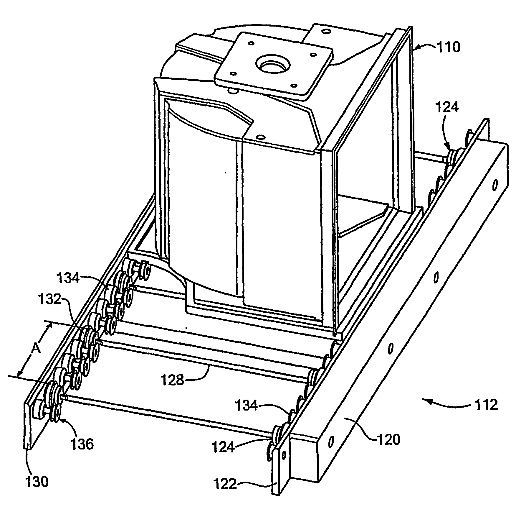
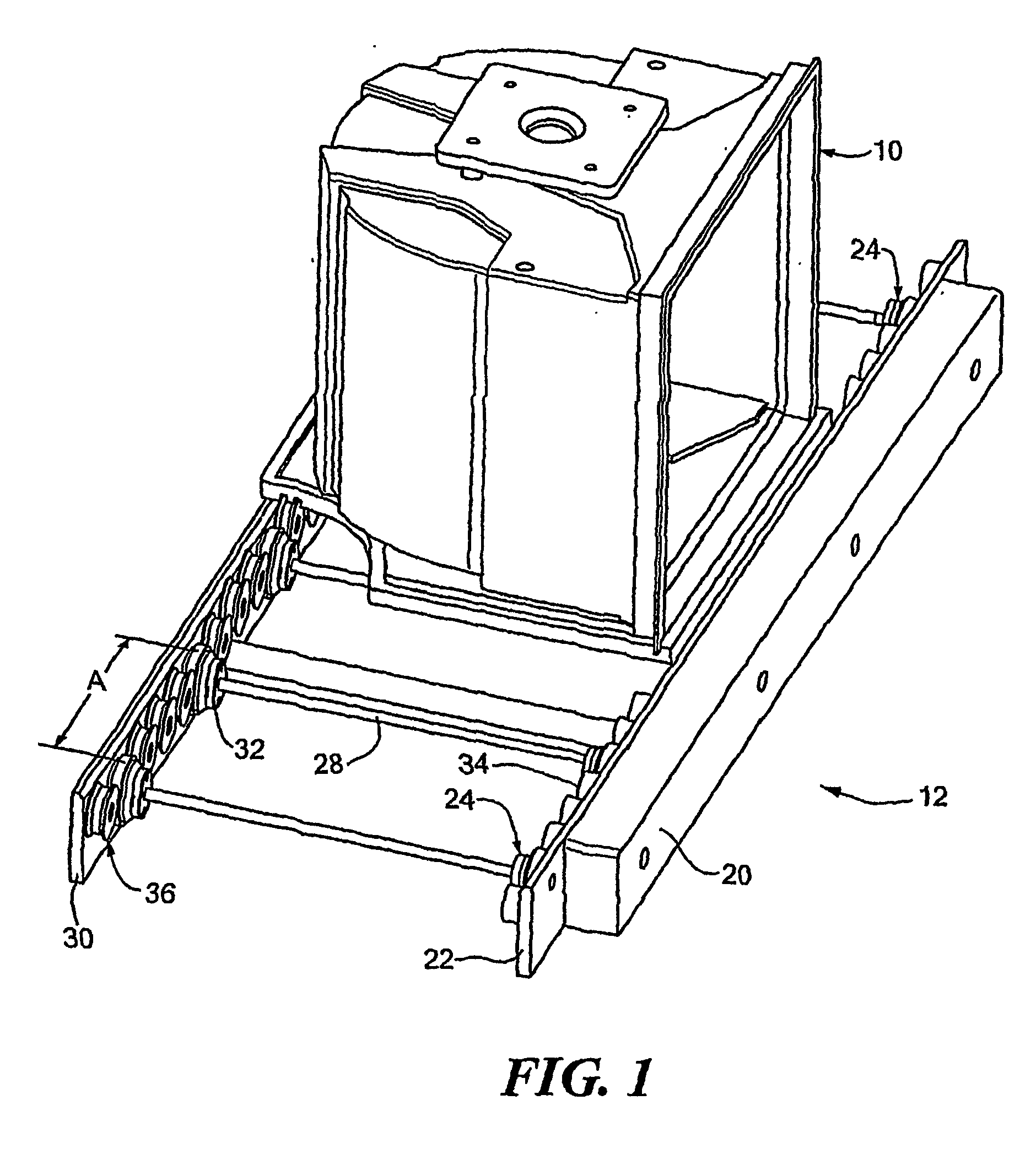
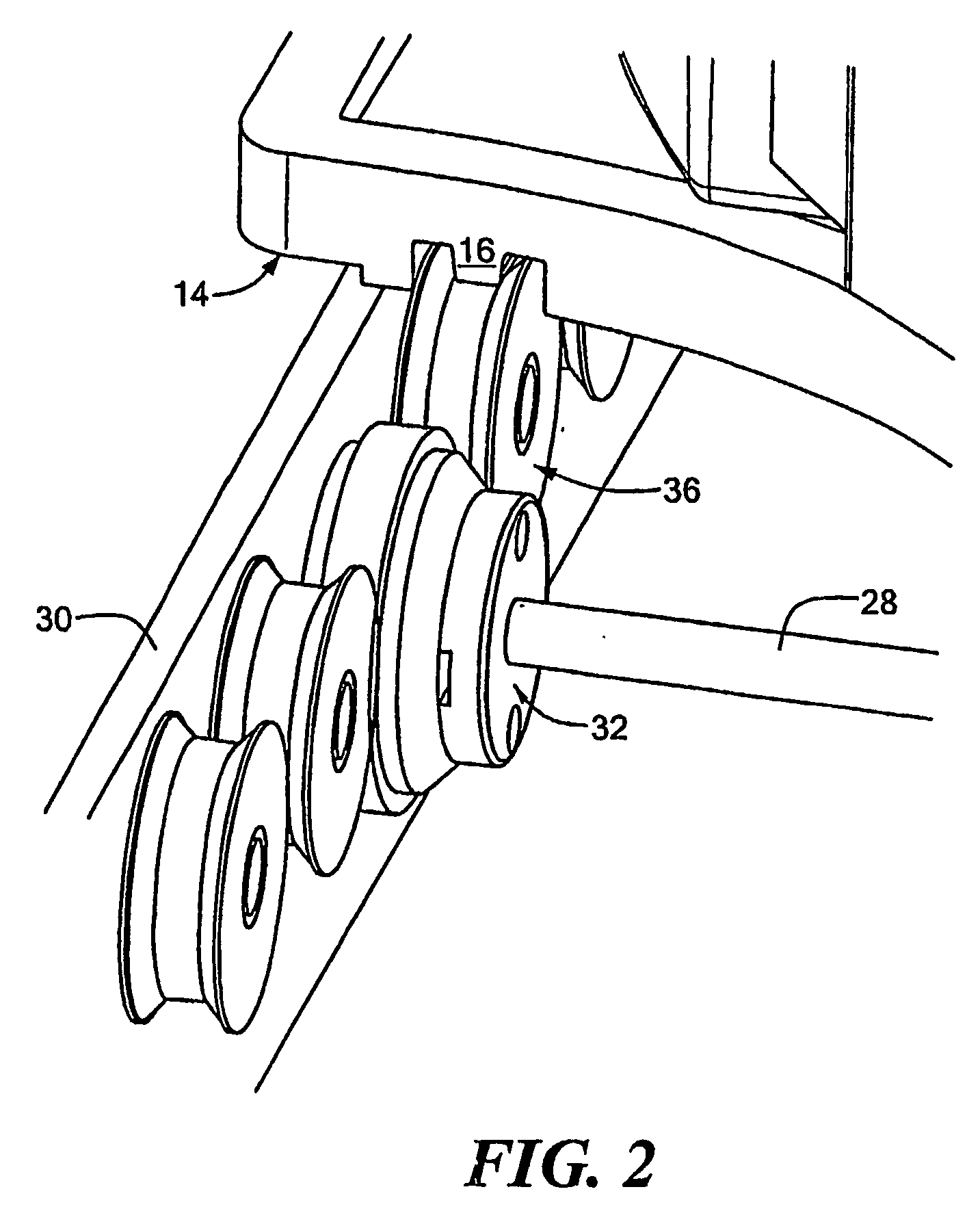
[0025] The present invention is useful for transporting sensitive materials in a clean room. In a first embodiment, the invention is directed to the conveyor system shown in FIGS. 1-4. The system includes a carrier 10 and a conveyor assembly 12. The bottom surface 14 of the carrier has a rib 16 that is parallel to the direction of travel of the carrier. This rib extends the length of the carrier bottom surface. The rib may be recessed so as to not extend beyond the bottom surface of the carrier, may be flush with the bottom surface, or may extend beyond the bottom surface. While a recessed rib may be less likely to interfere with other components of the carrier system and may experience less wear, a projecting rib may be useful for supporting the carrier on a solid surface. The rib preferably has a square or rectangular cross-section.

[0026] Alternative embodiments of the rib may include designs in which the rib does- not extend the length of the carrier 10 or those that have a plur...


PUM


Abstract

A conveyor system and method that reduces extraneous forces in a manufacturing process is disclosed. The system and method of the invention are particularly directed to handling and processing sensitive materials such as, for example, in clean room manufacturing facilities. These facilities are used in the fields of semiconductor fabrication, hard disk drive manufacturing, biotechnology, biomedical engineering and pharmaceutical engineering. A conveyor system according to the invention includes a carrier and a drive assembly for providing relative movement thereto. A rib or groove extends along the bottom of the carrier parallel to the direction of travel. The rib and groove structures are also intended to reduce mechanical contact between the carrier and the drive assembly, including its components. A reduction of such contact limits the extent of contamination caused by particulate formation.

Description

CROSS REFERENCE TO RELATED APPLICATIONS [0001] This application claims the priority of U.S. Provisional Application No. 60 / 484,789 filed on Jul. 3, 2003 entitled, CLEAN ROOM GUIDED CONVEYOR, the whole of which is hereby incorporated by reference herein.STATEMENT REGARDING FEDERALLY SPONSORED RESEARCH OR DEVELOPMENT [0002] Not applicable. BACKGROUND OF THE INVENTION [0003] In general, most manufacturing processes include automated operations to improve efficiency and overall product quality. One concern with automation is that materials or products may be mishandled or damaged. These concerns are more significant for manufacturing processes involving sensitive materials such as, for example, in the fields of semiconductor fabrication, hard disk drive manufacturing, biotechnology, biomedical engineering and pharmaceutical engineering. [0004] These fields commonly use clean room facilities to reduce the likelihood of the process becoming contaminated. Contamination is a particular issu...

Claims


Application Information

Patent Timeline
Patent Type & Authority Applications(United States)
IPC IPC(8): A61K51/00H01L21/677
CPCB65G13/02B65G39/02H01L21/67706H01L21/6773
Inventor PYKE, ADRIAN L.LEBO, WILLIAMT
Owner MIDDLESEX GEN INDS MESNE
Why Eureka
Try Eureka