High gas yield non-azide gas generants

Inactive Publication Date: 2001-04-03
AUTOMOTIVE SYST LAB
View PDF17 Cites 78 Cited by
  • Summary
  • Abstract
  • Description
  • Claims
  • Application Information

AI Technical Summary

Problems solved by technology

The gas generant compositions described in Poole et al, U.S. Pat. Nos. 4,909,549 and 4,948,439, use tetrazole or triazole compounds in combination with metal oxides and oxidizer compounds (alkali metal, alkaline earth metal, and pure ammonium nitrates or perchlorates) resulting in a relatively unstable generant that decomposes at low temperatures.
Significant toxic emissions and particulate are formed upon combustion.
The gas generant compositions described in Poole, U.S. Pat. No. 5,035,757, result in more easily filterable solid products but the gas yield is unsati

Method used


Image

  • High gas yield non-azide gas generants
  • High gas yield non-azide gas generants
  • High gas yield non-azide gas generants

Examples


Example

EXAMPLE 16--Illustrative

Phase-stabilized ammonium nitrate (PSAN) consisting of 85 wt % ammonium nitrate (AN) and 15 wt % potassium nitrate (KN) was prepared as follows. 2125 g of dried AN and 375 g of dried KN were added to a heated jacket double planetary mixer. Distilled water was added while mixing until all of the AN and KN had dissolved and the solution temperature was 66-70.degree. C. Mixing was continued at atmospheric pressure until a dry, white powder formed. The product was PSAN. The PSAN was removed from the mixer, spread into a thin layer, and dried at 80.degree. C. to remove any residual moisture.

Example

EXAMPLE 17--Illustrative

The PSAN prepared in example 16 was tested as compared to pure AN to determine if undesirable phase changes normally occurring in pure AN had been eliminated. Both were tested in a DSC from 0.degree. C. to 200.degree. C. Pure AN showed endotherms at about 57.degree. C. and about 133.degree. C., corresponding to solid-solid phase changes as well as a melting point endotherm at about 170.degree. C. PSAN showed an endotherm at about 118.degree. C. corresponding to a solid-solid phase transition and an endotherm at about 160.degree. C. corresponding to the melting of PSAN.

Pure AN and the PSAN prepared in example 16 were compacted into 12 mm diameter by 12 mm thick slugs and measured for volume expansion by dilatdmetry over the temperature range -40.degree. C. to 140.degree. C. When heating from -40.degree. C. to 140.degree. C. the pure AN experienced a volume contraction beginning at about -34.degree. C., a volume expansion beginning at about 44.degree. C., and a...

Example

EXAMPLE 18

A mixture of PSAN and BHT.2NH.sub.3 was prepared having the following composition in percent by weight: 76.43% PSAN and 23.57% BHT.2NH.sub.3. The weighed and dried components were blended and ground to a fine powder by tumbling with ceramic cylinders in a ball mill jar. The powder was separated from the grinding cylinders and granulated to improve the flow characteristics of the material. The granules were compression molded into pellets on a high speed rotary press. Pellets formed by this method were of exceptional quality and strength.

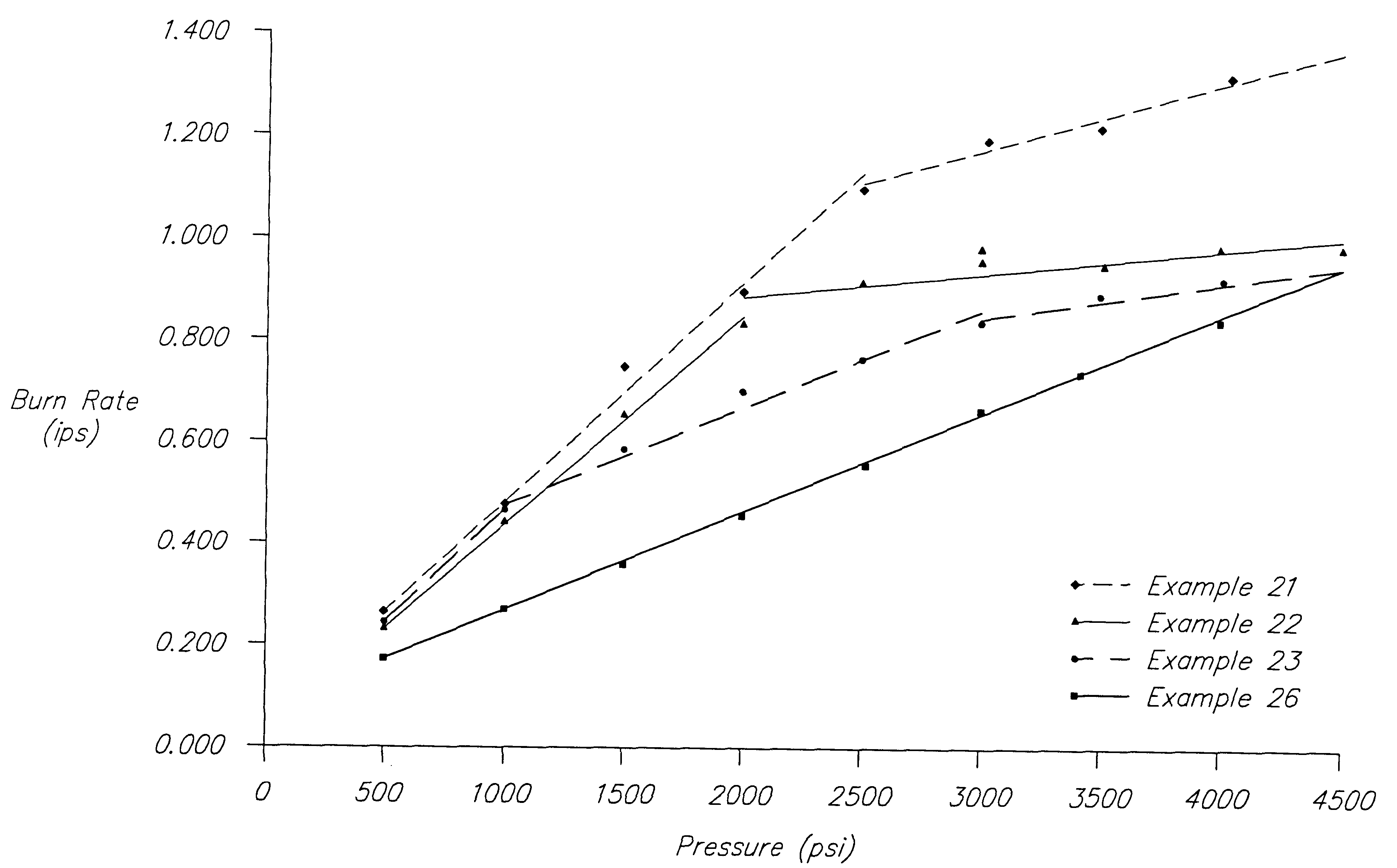
The burn rate of the composition was 0.48 inches per second at 1000 psi. The burn rate was determined by measuring the time required to burn a cylindrical pellet of known length at a constant pressure. The pellets were compression molded in a 1 / 2" diameter die under a 10 ton load, and then coated on the sides with an epoxy / titanium dioxide inhibitor which prevented burning along the sides.

The pellets formed on the rotary press were loaded i...


PUM


Abstract

High nitrogen nonazide gas compositions, useful in inflating passenger restraint gas inflator bags, comprise a nonmetal salt of triazole or tetrazole fuel, phase stabilized ammonium nitrate (PSAN) as a primary oxidizer, a metallic second oxidizer, and an inert component such as clay or mica. The combination of these constituents results in gas generants that are relatively more stable and less explosive, have improved ignitability and satisfactory burn rates, have sustained combustion throughout the various combustion pressures at the inflator level, and generate more gas and less solids than known gas generant compositions.

Description

The present invention relates to nontoxic gas generating compositions which upon combustion, rapidly generate gases that are useful for inflating occupant safety restraints in motor vehicles and specifically, the invention relates to nonazide gas generants that produce combustion products having not only acceptable toxicity levels, but that also exhibit a relatively high gas volume to solid particulate ratio at acceptable flame temperatures. Additionally, the compositions of the present invention readily ignite and sustain combustion at burn rates heretofore thought to be too low for automotive airbag applications.The evolution from azide-based gas generants to nonazide gas generants is well-documented in the prior art. The advantages of nonazide gas generant compositions in comparison with azide gas generants have been extensively described in the patent literature, for example, U.S. Pat. Nos. 4,370,181; 4,909,549; 4,948,439; 5,084,118; 5,139,588 and 5,035,757, the discussions of w...

Claims


Application Information

Patent Timeline
IPC IPC(8): C06D5/00C06D5/06B60R21/26C06B31/28
CPCC06D5/06
Inventor KHANDHADIA, PARESH S.BURNS, SEAN P.WILLIAMS, GRAYLON K.
Owner AUTOMOTIVE SYST LAB
Why Eureka
Try Eureka