
Forward-based power conversion apparatus

a power conversion apparatus and forward-based technology, applied in the direction of power conversion systems, dc-dc conversion, instruments, etc., can solve the problems of increasing the reducing and reducing the overall power loss of the power conversion apparatus. , the effect of improving the conversion efficiency of the power conversion apparatus

Active Publication Date: 2017-02-14
SPI ELECTRONICS
View PDF5 Cites 0 Cited by
  • Summary
  • Abstract
  • Description
  • Claims
  • Application Information

AI Technical Summary

Benefits of technology

The patent describes a power conversion apparatus that can generate multiple output voltages using a transformer. By capturing the reverse voltage of the secondary winding of the transformer and converting it into an effective power output, the overall power loss of the apparatus is reduced and the conversion efficiency is improved. This results in a more efficient and effective power conversion.

Problems solved by technology

In general, when the forward-based power conversion apparatus supplies an output voltage to a load, a reverse voltage of a secondary winding of a transformer is always not used in an effective manner and is accordingly wasteful.
On said condition, the overall power loss of the power conversion apparatus may increase, thus lessening the conversion efficiency of the power conversion apparatus.

Method used


Image

  • Forward-based power conversion apparatus
  • Forward-based power conversion apparatus
  • Forward-based power conversion apparatus

Examples


Embodiment Construction

[0023]Descriptions of the invention are given with reference to the exemplary embodiments illustrated with accompanied drawings, wherein same or similar parts are denoted with same reference numerals. In addition, whenever possible, identical or similar reference numbers stand for identical or similar elements in the figures and the exemplary embodiments.

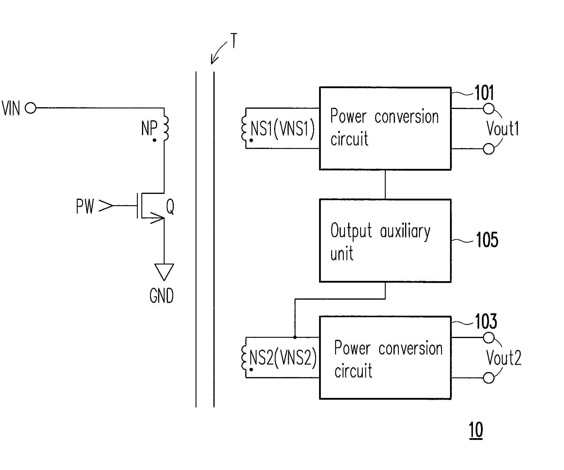
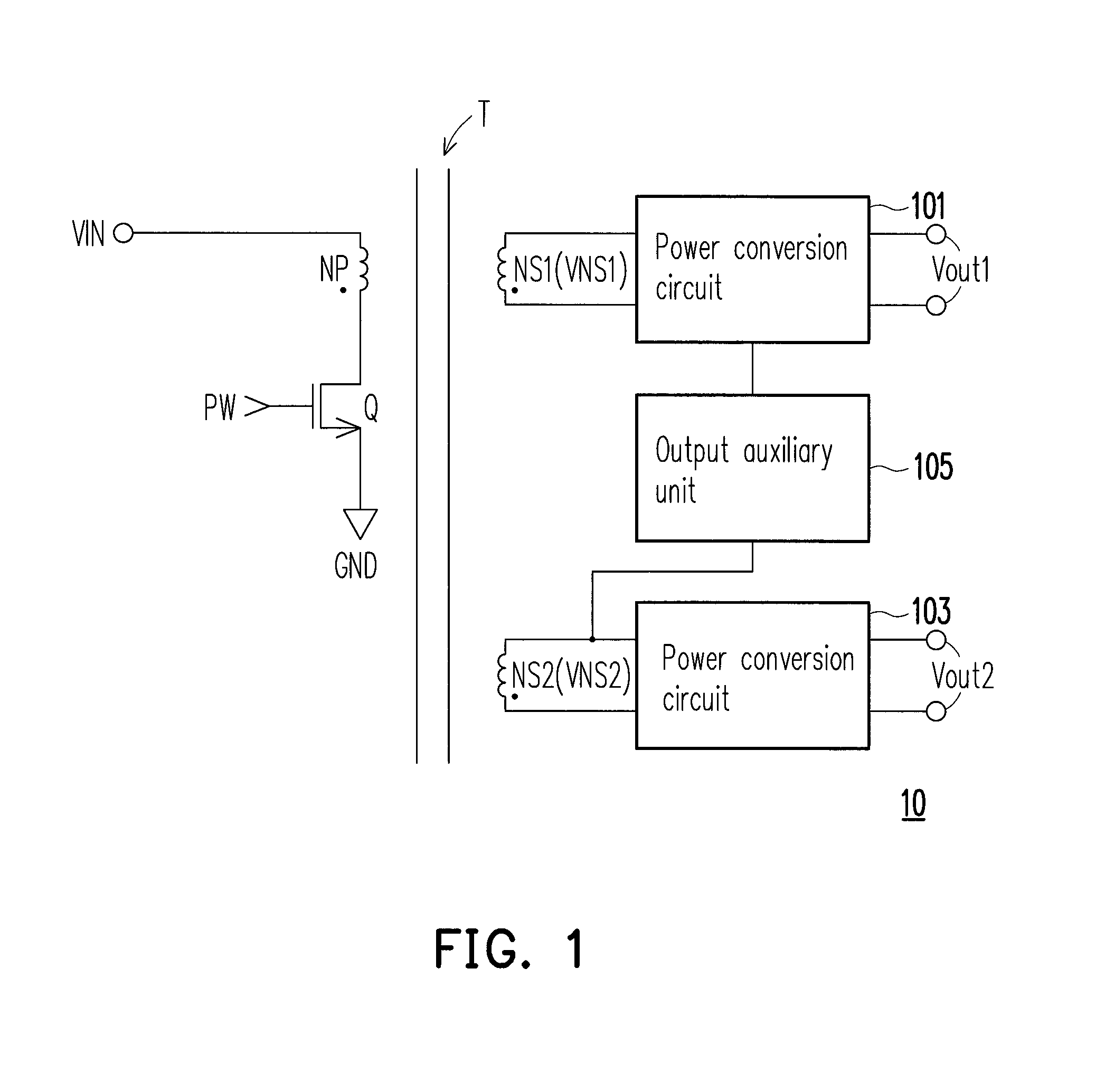
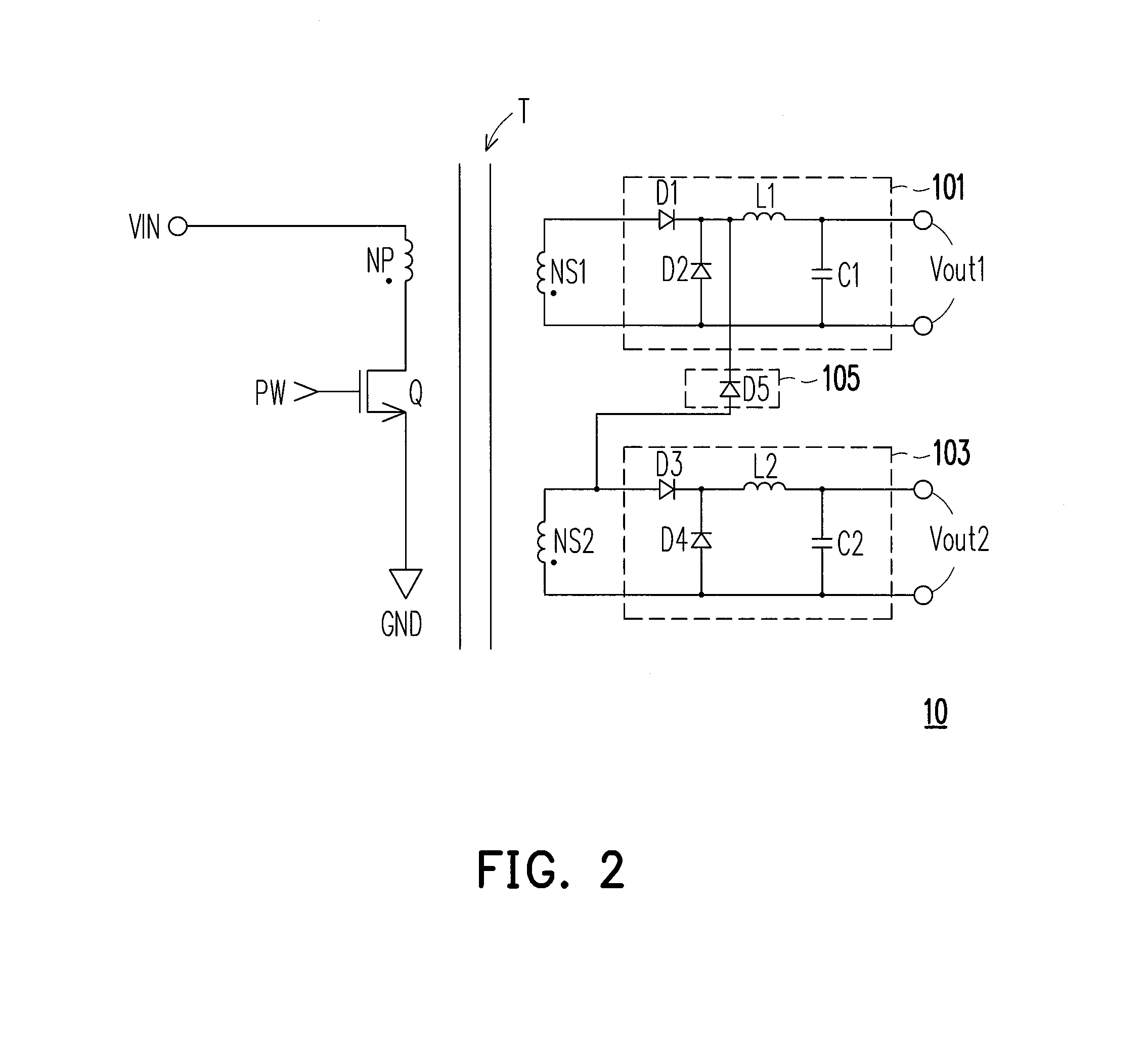
[0024]FIG. 1 is a schematic diagram of a power conversion apparatus 10 according to an exemplary embodiment of the invention. With reference to FIG. 1, the power conversion apparatus 10 includes a transformer T, a power switch Q, power conversion circuits 101 and 103, and an output auxiliary unit 105. In the present exemplary embodiment, the transformer T has a primary winding NP, a first secondary winding NS1, and a second secondary winding NS2. An opposite-polarity terminal (i.e., the non-dotted terminal) of the primary winding NP of the transformer T receives an input voltage VIN (i.e., a direct input voltage).

[0025]A first termi...


PUM


Abstract

A forward-based power conversion apparatus is provided. When the forward-based power conversion apparatus supplies a plurality of (at least two of) output voltages to a load, a reverse voltage, corresponding to a lower output voltage, of a secondary winding of a transformer is captured through an equipped output auxiliary unit, so as to assist an output of a higher output voltage. Accordingly, compared to that described in the related art, the reverse voltage of the secondary winding of the transformer described herein can be converted into an effective power output, so that overall power loss of the power conversion apparatus can be reduced, and conversion efficiency of the power conversion apparatus can be improved.

Description

CROSS-REFERENCE TO RELATED APPLICATION[0001]This application claims the priority benefit of Taiwan application serial no. 101132541, filed on Sep. 6, 2012. The entirety of the above-mentioned patent application is hereby incorporated by reference herein and made a part of this specification.BACKGROUND OF THE INVENTION[0002]Field of the Invention[0003]The invention relates to a power conversion technique; more particularly, the invention relates to a forward-based power conversion apparatus.[0004]Description of Related Art[0005]One of the common power conversion apparatuses is a forward-based power conversion apparatus. In general, when the forward-based power conversion apparatus supplies an output voltage to a load, a reverse voltage of a secondary winding of a transformer is always not used in an effective manner and is accordingly wasteful. On said condition, the overall power loss of the power conversion apparatus may increase, thus lessening the conversion efficiency of the pow...

Claims


Application Information

Patent Timeline
Patent Type & Authority Patents(United States)
IPC IPC(8): H02J3/00H02M3/335
CPCH02M3/33553H02M3/33561Y10T307/297
Inventor SHIH, YUNG-HSIANGCHIANG, CHANG-HSUN
Owner SPI ELECTRONICS
Learn More