Object information acquiring apparatus

a technology of object information and acquisition apparatus, which is applied in the field of object information acquisition apparatus, can solve the problems of inability to acquire preset number of elements in a region, inability to perform imaging with respect, etc., and achieve the effect of enlarge the acquired image region

Active Publication Date: 2017-02-21
CANON KK
View PDF10 Cites 0 Cited by
  • Summary
  • Abstract
  • Description
  • Claims
  • Application Information

AI Technical Summary

Benefits of technology

[0015]In accordance with the present invention, it is possible to enlarge the acquired image region in an apparatus that acquires the image of an object by mechanically scanning a probe and transmitting and receiving ultrasound waves.

Problems solved by technology

However, with such a method, imaging is impossible with respect to a region in which the preset number of elements cannot be obtained, such as an object region located on the front surface of the end sections of a probe.
The resultant problem is that even when a wide-range image region is acquired by mechanically scanning the probe, imaging is not performed with respect to the three-dimensional region located on the front surface of the end section of the probe.

Method used


Image

  • Object information acquiring apparatus
  • Object information acquiring apparatus
  • Object information acquiring apparatus

Examples


embodiment 1

Configuration of the Apparatus

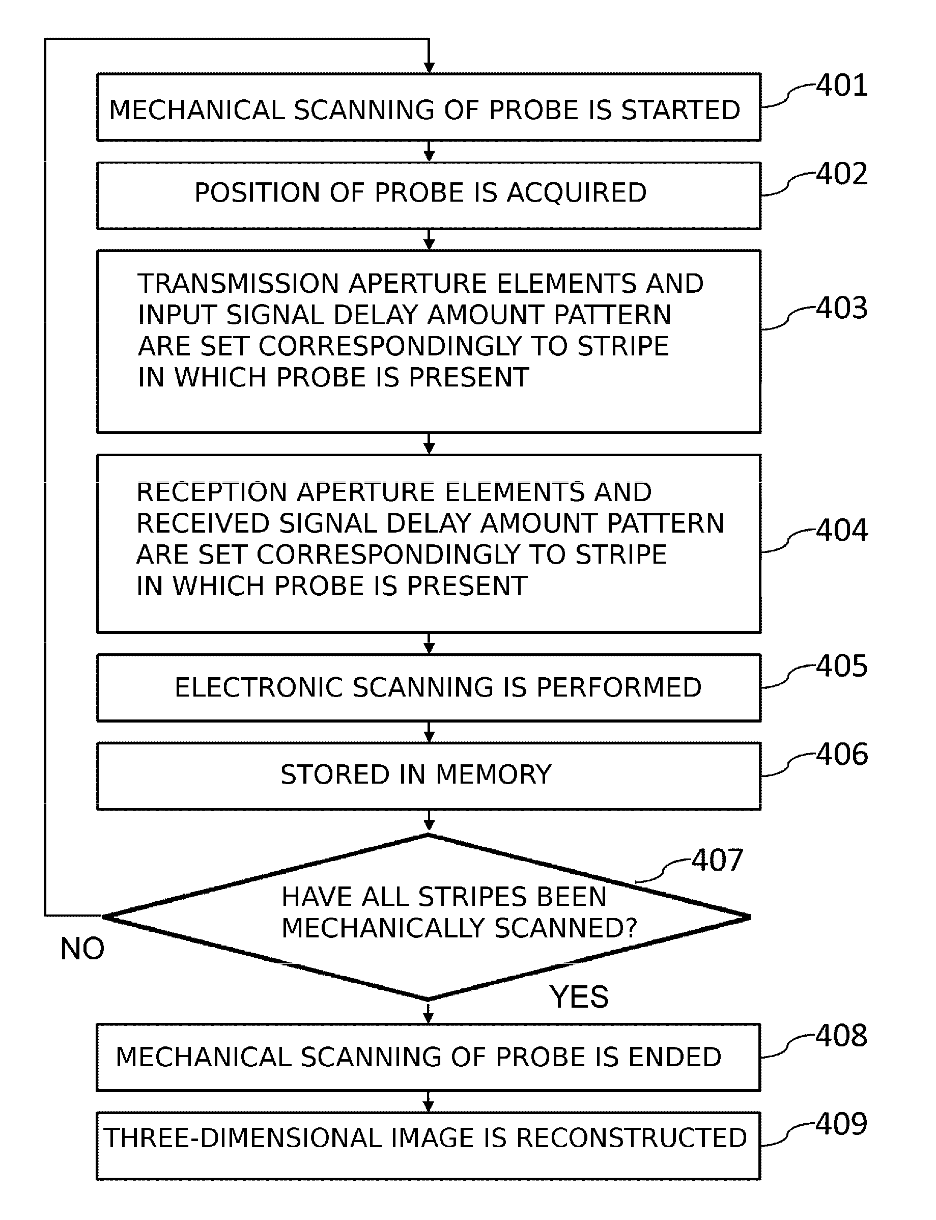
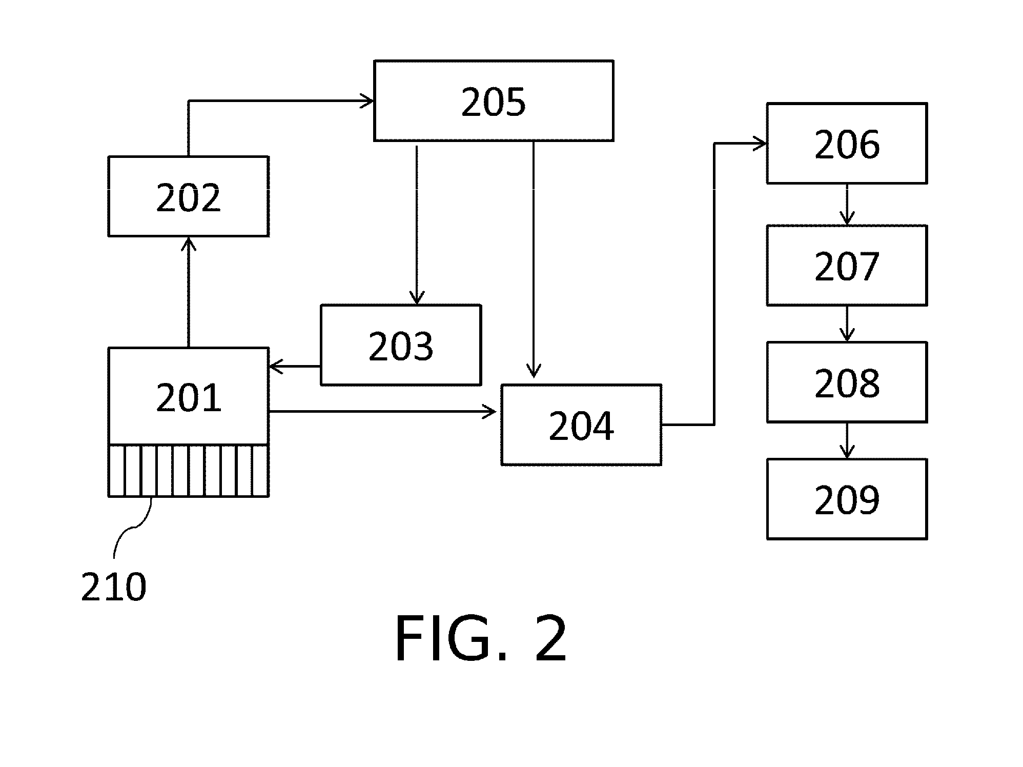
[0044]FIG. 2 shows the configuration of the object information acquiring apparatus in accordance with the present invention. The apparatus is provided with a probe 201, a mechanical scanning mechanism 202 for the probe, a transmitting processing unit 203, a received signal processing unit 204, a control unit 205, an image processing unit 206, an image memory 207, an image reconstruction unit 208, and an image display unit 209. A transducer array 210 with one-dimensional arrangement of elements is provided on the probe 201.

[0045]As mentioned hereinabove, an ultrasound transmission / reception beam from the aperture elements on the transducer array 210 is electronically scanned over a tomographic surface and a tomographic image is produced. The probe 201 is fixed to a movable section of the mechanical scanning mechanism 202 and moves together with the movable section. The transmitting processing unit 203 switches aperture elements that are to be driven, gen...

embodiment 2

[0074]In the method explained in Embodiment 1, the number of aperture elements is changed in order to enlarge the imaging region in the secondary scanning direction in the end section of the mechanically scannable range (the end portion of the measurement target region of the object).

[0075]In the present embodiment, by contrast with Embodiment 1, when the probe is positioned in the end section of the secondary scanning range (stripe), the transmitted / received ultrasound beam is deflected to enlarge the tomographic image region.

[0076]FIG. 7 is a conceptual diagram of an input signal for deflecting the transmitted beam. As shown in FIG. 7A, where a pulse signal 701 is inputted into each element of the transmission aperture element row 702 at the same timing, the transmitted ultrasound beam is formed in a direction 703 orthogonal to the element arrangement direction in the transmission aperture element row 702. A position for converging the ultrasound wave can be also set by providing ...

embodiment 3

[0080]In the present embodiment, the mechanical scanning range of the probe is not set at the apparatus side, and an examiner determines the desired mechanical scanning range (examiner's setting range) by using input means.

[0081]Displaying the object picked up with a camera at the image and indicating the examiner's setting range on the image can be used as the input means for the examiner's setting range. The image pickup means is not limited to the camera and other medical diagnostic devices may be also used.

[0082]FIG. 9 is a conceptual diagram illustrating the relationship of image regions acquired by mechanical scanning of an examiner's setting range 902 and the probe 201 (901). A stripe region 903 is superimposed on the examiner's setting range 902 by mechanically scanning the probe 201 in the main scanning direction and secondary scanning direction in the same manner as in Embodiment 1. In this case, a non-imaging stripe region 904 is generated in the mechanical scanning range...


PUM


Abstract

Provided is an object information acquiring apparatus including a probe in which a plurality of elements transmitting an ultrasound wave to a measurement target region of an object and receiving a reflected wave is arranged in a first direction, and a mechanical scanning unit that moves the probe in the first direction and a direction crossing the first direction. A transmission processor, to each element included in a transmission aperture element row transmitting the ultrasound wave, inputs an input signal for driving the element, and a received signal processor combines received signals obtained by the elements included in a reception aperture element row receiving the ultrasound wave. A generator generates property information on the object from the combined signal, and a controller that determines at least one of the number of elements included in the transmission aperture element row.

Description

BACKGROUND OF THE INVENTION[0001]Field of the Invention[0002]The present invention relates to an object information acquiring apparatus.[0003]Description of the Related Art[0004]An apparatus for acquiring object information is known in which an ultrasound beam is transmitted toward an object, a reflected wave from inside the object is received, and the received signal is converted into an image. Japanese Patent Application Laid-Open No. 2009-028366 (Patent Literature 1) discloses a method for generating a three-dimensional ultrasound echo image of a wide region by mechanically scanning a probe in which elements transmitting and receiving ultrasound waves are arranged one-dimensionally. In the apparatus used in this method, a three-dimensional image can be configured by mechanically scanning the probe in a direction crossing the electronic scanning direction, while acquiring tomographic images by electronic scanning of the ultrasound transmitted / received beam. Such a method makes it ...

Claims


Application Information

Patent Timeline
Patent Type & Authority Patents(United States)
IPC IPC(8): A61B8/00A61B8/08G01S15/89G01S7/52
CPCA61B8/4466A61B8/4461A61B8/4494A61B8/483G01S7/52085G01S15/8915G01S15/8945A61B8/461
Inventor TAKAHASHI, HIROKIEBISAWA, HISAFUMI
Owner CANON KK
Why Eureka
Try Eureka