

Camera module
a technology of camera module and camera body, which is applied in the direction of camera focusing arrangement, printers, instruments, etc., can solve the problems of increasing the overall size of the conventional camera module, high power consumption of the lens-moving apparatus, etc., and achieves the improvement of the resolution of the peripheral region of the image acquired through the image sensor, the effect of enhancing the accuracy of the function and enhancing the effect of the function
Pending Publication Date: 2021-02-04
LG INNOTEK CO LTD
View PDF3 Cites 1 Cited by
- Summary
- Abstract
- Description
- Claims
- Application Information
AI Technical Summary
Benefits of technology
The camera module described in this patent has two main benefits. First, it uses a liquid lens unit for on-focus autofocus (AF) and a separate lens-moving unit for optical image stabilization (OIS) which improves image quality. Second, it uses multiple wires instead of a magnet for OIS, making it smaller and suitable for use in dual-camera modules.
Problems solved by technology
However, the lens-moving apparatus has high power consumption, and an additional cover glass needs to be provided separately from a camera module in order to protect the lens-moving apparatus, thus causing a problem in that the overall size of the conventional camera module increases.
Method used
View moreImage
Smart ImageViewing Examples

Examples
Embodiment Construction
[0193]Various embodiments have been described in the best mode for carrying out the disclosure.
Industrial Applicability
[0194]A camera module according to embodiments may be used in camera / video devices, telescopic devices, microscopic devices, an interferometer, a photometer, a polarimeter, a spectrometer, a reflectometer, an auto-collimator, a lens-meter, a smartphone, a laptop computer, a tablet computer, etc.
Login to View More PUM
 Abstract
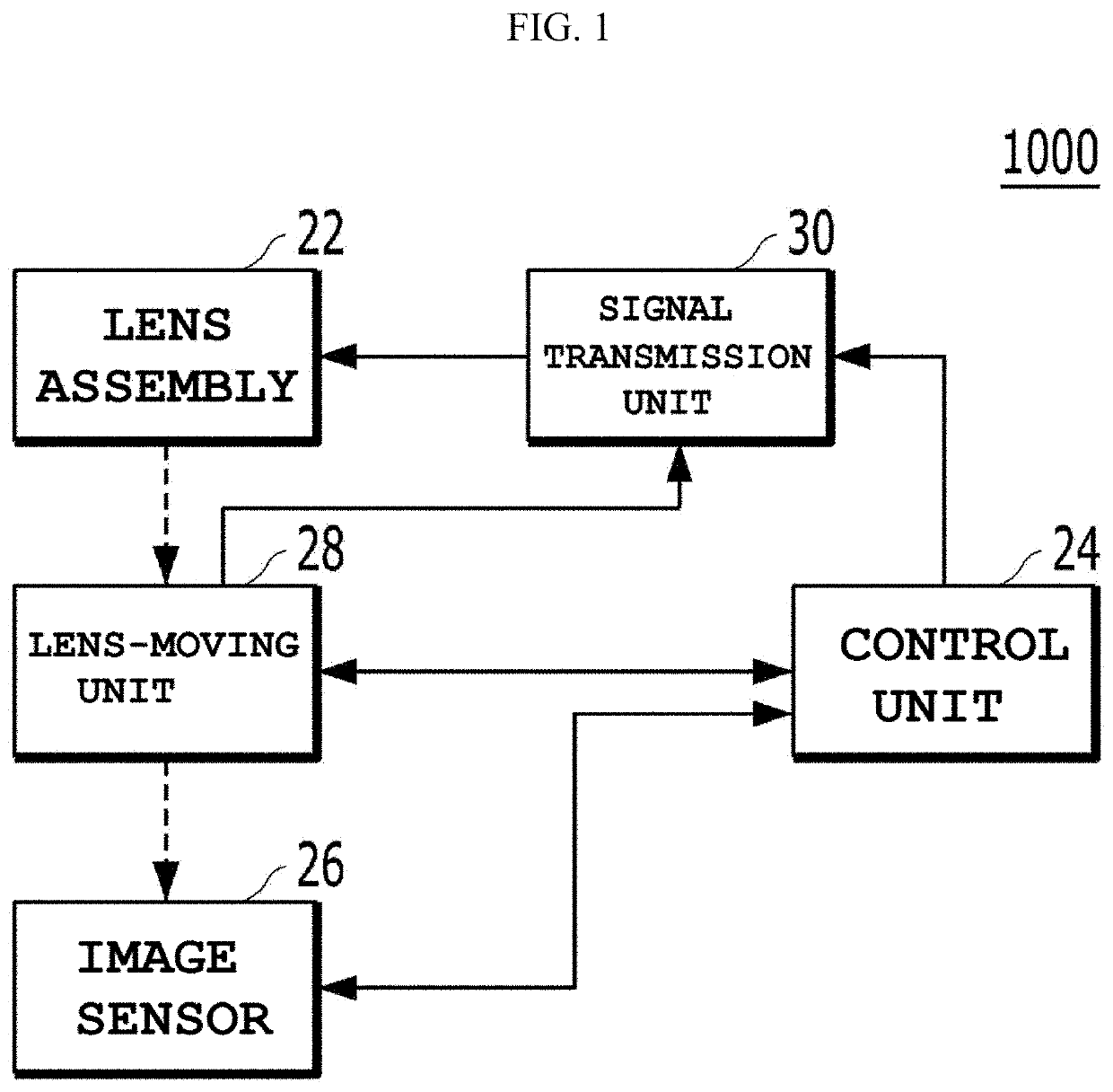
A camera module includes a lens assembly accommodating a liquid lens unit, and a lens-moving unit disposed along an optical axis between the lens assembly and an image sensor, the lens-moving unit being configured to move the lens assembly in a horizontal direction perpendicular to the optical axis of the liquid lens unit in response to a horizontal control signal, wherein the lens-moving unit includes a fixed body, a moving body disposed on the fixed body so as to be movable in the horizontal direction, and a plurality of wires configured to contract or expand independently of each other so as to move the moving body in the horizontal direction in response to the horizontal control signal, each of the plurality of wires including one end connected to the fixed body and an opposite end connected to the moving body.
Description
CROSS-REFERENCE TO RELATED APPLICATIONS[0001]This application is the U.S. national stage application of International Patent Application No. PCT / KR2019 / 000937, filed Jan. 23, 2019, which claims the benefit under 35 U.S.C. § 119 of Korean Patent Application No. 10-2018-0008998, filed Jan. 24, 2018, the disclosures of each of which are incorporated herein by reference in their entirety.TECHNICAL FIELD[0002]Embodiments relate to a camera module.BACKGROUND ART[0003]People who use portable devices demand optical devices that have high resolution, are small, and have various photographing functions. For example, these various photographing functions may be at least one of an optical zoom-in / zoom-out function, an auto-focusing (AF) function, or a hand-tremor compensation or optical image stabilizer (OIS) function.[0004]In a conventional art, in order to implement the above-described various photographing functions, a method of combining a plurality of lenses and directly moving the combine...
Claims
Login to View More Application Information
Patent Timeline
 Patent Type & AuthorityApplications(United States)
IPC IPC(8): G02B26/00G02B3/14G02B7/09G03B13/36G02B27/64G03B5/00
CPCG02B26/004G02B3/14G02B7/09G03B2205/0007G02B27/646G03B5/00G03B13/36G02B3/12G03B3/10G03B2205/0015G03B2205/0053G03B30/00H04N23/55G03B17/12
InventorPARK, JAE KEUN
OwnerLG INNOTEK CO LTD