Pulsed valve manifold for atomic layer deposition

Active Publication Date: 2017-02-21
ASM IP HLDG BV
View PDF139 Cites 316 Cited by
  • Summary
  • Abstract
  • Description
  • Claims
  • Application Information

AI Technical Summary

Benefits of technology

[0010]The systems and methods of the present invention have several features, no single one of which is solely responsible for its desirable attributes. Without limiting the scope of this invention as expressed by the claims which follow, its more prominent features will now be discu

Problems solved by technology

The process is self-limiting because the vapor phase precursor cannot react with or adsorb upon the adsorbed portion of the precursor.
Designin

Method used


Image

  • Pulsed valve manifold for atomic layer deposition
  • Pulsed valve manifold for atomic layer deposition
  • Pulsed valve manifold for atomic layer deposition

Examples


Embodiment Construction

,” one will understand how the features described herein provide several advantages over traditional ALD gas delivery methods and systems.

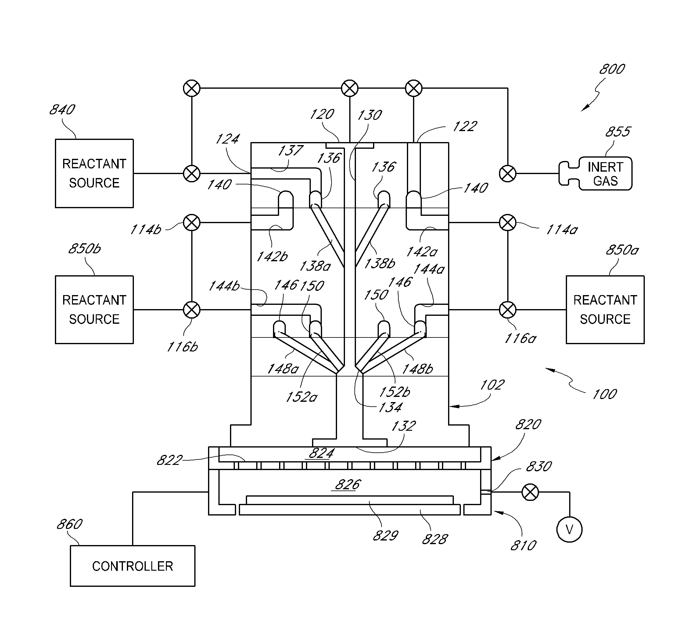
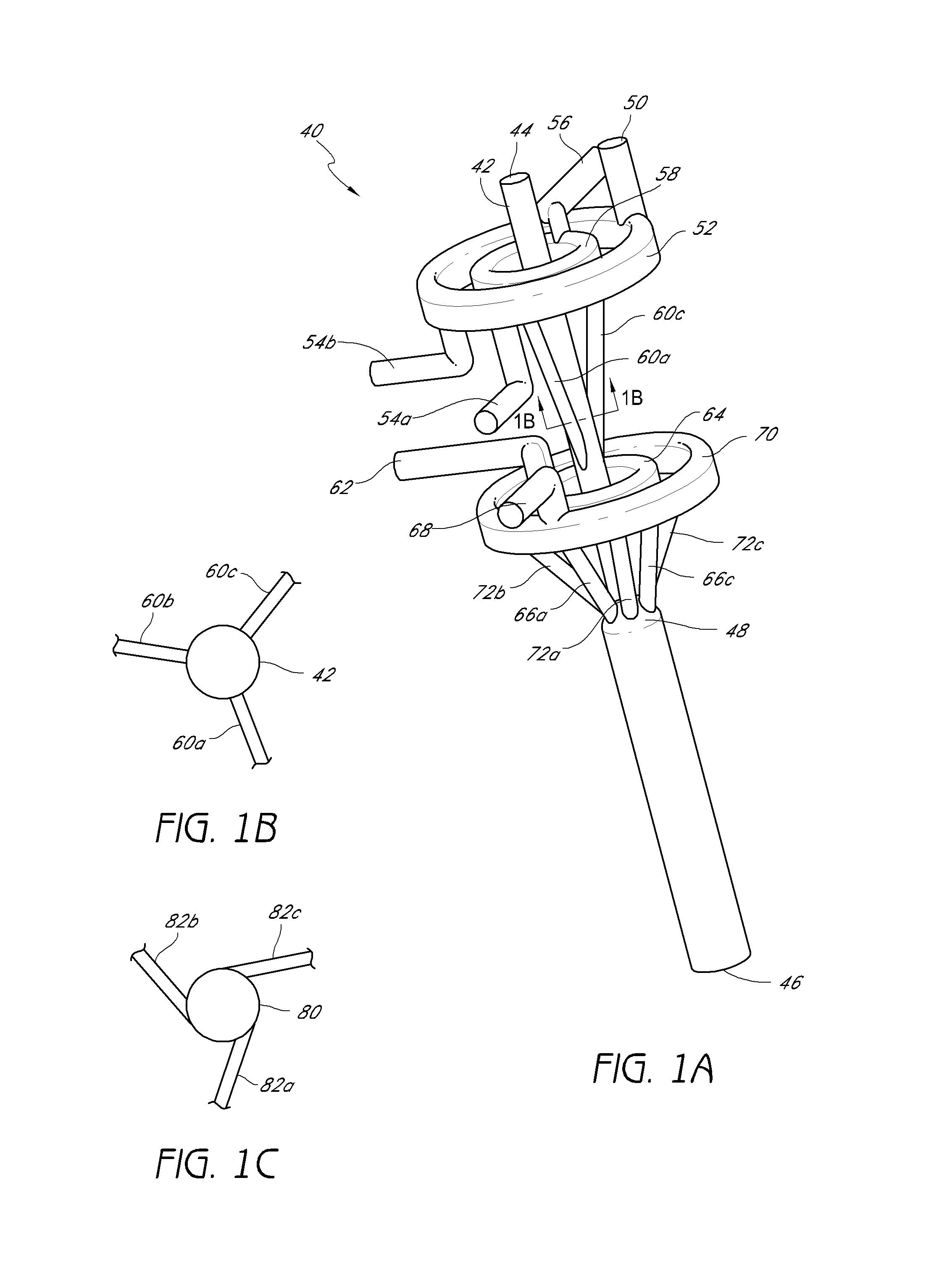
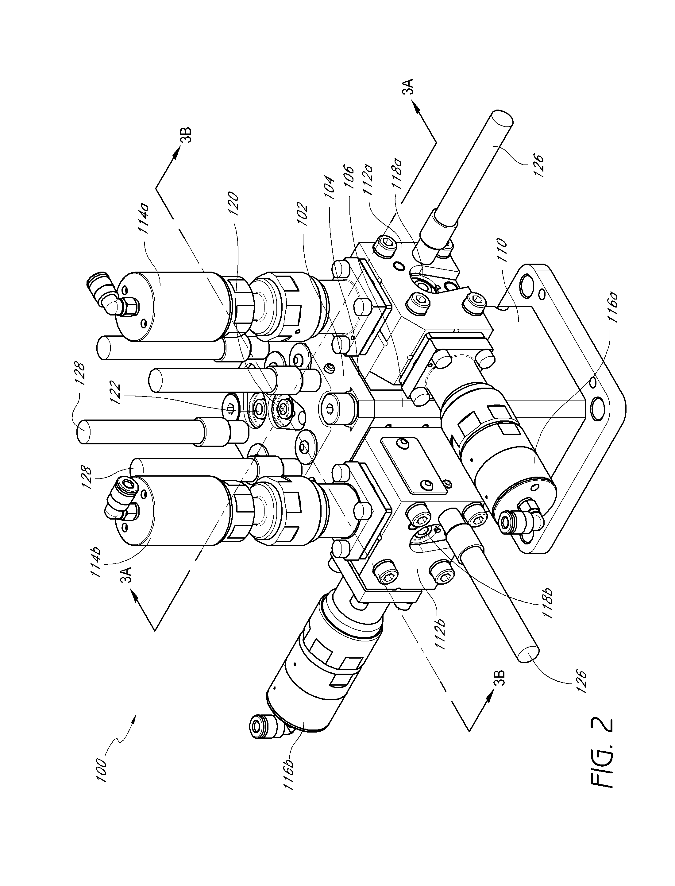
[0011]One aspect is a vapor deposition device including a reactor including a reaction chamber and an injector configured to inject vapor into the reaction chamber and a manifold configured to deliver vapor to the injector, the manifold being disposed upstream of the injector. The manifold includes a manifold body having a bore disposed within the body, the bore having a longitudinal axis; a first distribution channel disposed within the body and extending in a plane intersecting the longitudinal axis; and a plurality of first supply channels disposed within the body and in flow communication with the first distribution channel and with the bore, each of the first supply channels being disposed at an acute angle with respect to the longitudinal axis of the bore, each of the first supply channels connecting with the bore at a different angular posi...


PUM

PropertyMeasurementUnit
Fractionaaaaaaaaaa
Fractionaaaaaaaaaa
Angleaaaaaaaaaa

Abstract

A vapor deposition device includes a reactor including a reaction chamber and an injector for injecting vapor into the reaction chamber. The device also includes a manifold for delivering vapor to the injector. The manifold includes a manifold body having an internal bore, a first distribution channel disposed within the body in a plane intersecting the longitudinal axis of the bore, and a plurality of supply channels disposed within the body and in flow communication with the first distribution channel and with the bore. Each of the first supply channels is disposed at an acute angle with respect to the longitudinal axis of the bore, and each of the supply channels connects with the bore at a different angular position about the longitudinal axis. The distribution channel (and thus, the supply channels) can be connected with a common reactant source. Related deposition methods are also described.

Description

BACKGROUND OF THE INVENTION[0001]Field of the Invention[0002]This application relates generally to semiconductor processing equipment and specifically to an apparatus for delivering vapors in an atomic layer deposition (ALD) device.[0003]Description of the Related Art[0004]There are several vapor deposition methods for depositing thin films on the surface of substrates. These methods include vacuum evaporation deposition, Molecular Beam Epitaxy (MBE), different variants of Chemical Vapor Deposition (CVD) (including low-pressure and organometallic CVD and plasma-enhanced CVD), and Atomic Layer Deposition (ALD).[0005]In an ALD process, one or more substrates with at least one surface to be coated are introduced into the reactor or deposition chamber. The substrate is heated to a desired temperature, typically above the condensation temperatures of the selected vapor phase reactants and below their thermal decomposition temperatures. One reactant is capable of reacting with the adsorbe...

Claims


Application Information

Patent Timeline
IPC IPC(8): C23C16/455C23C16/453
CPCC23C16/45512C23C16/45565C23C16/45574C23C16/455C23C16/45563C23C16/45576C23C16/45544C23C16/45561C23C16/4557C23C16/45589H01L21/0228H01L21/0262H01L21/28556
Inventor DUNN, TODDWHITE, CARLHALPIN, MIKESHERO, ERICTERHORST, HERBERTWINKLER, JERRY
Owner ASM IP HLDG BV
Why Eureka
Try Eureka