
Solar-powered apparatus

a technology of solar energy and solar energy, applied in the direction of machines/engines, solar thermal energy generation, etc., can solve the problems of reducing the wear of the transmission apparatus and prolonging the service life of the device, so as to reduce the refraction of external sunlight, the effect of effectively absorbing the heat of sunligh

Inactive Publication Date: 2017-02-21
ZHEJIANG GONGSHANG UNIVERSITY
View PDF15 Cites 0 Cited by
  • Summary
  • Abstract
  • Description
  • Claims
  • Application Information

AI Technical Summary

Benefits of technology

The invention is a solar-powered apparatus that converts solar energy into kinetic energy using a memory function of memory alloy. It has advantages of simple structure and high utilization rate of solar energy in a unit area. The apparatus has a transmission apparatus which prevents external impurities from entering, reduces wear and prolongs service life. The alloy sheets, made of memory alloy, have deformation due to external force and can restore to the original shape at a certain temperature when the external force is canceled. The apparatus can be used in a variety of applications such as protecting the environment, development and utilization of new energy.

Problems solved by technology

The transmission apparatus is disposed inside the housing and connected with the alloy sheets, thereby preventing external impurities from entering into the transmission apparatus, reducing the wear of the transmission apparatus, and prolonging the service life of the device.

Method used


Image

  • Solar-powered apparatus
  • Solar-powered apparatus

Examples


embodiment 1

[0019

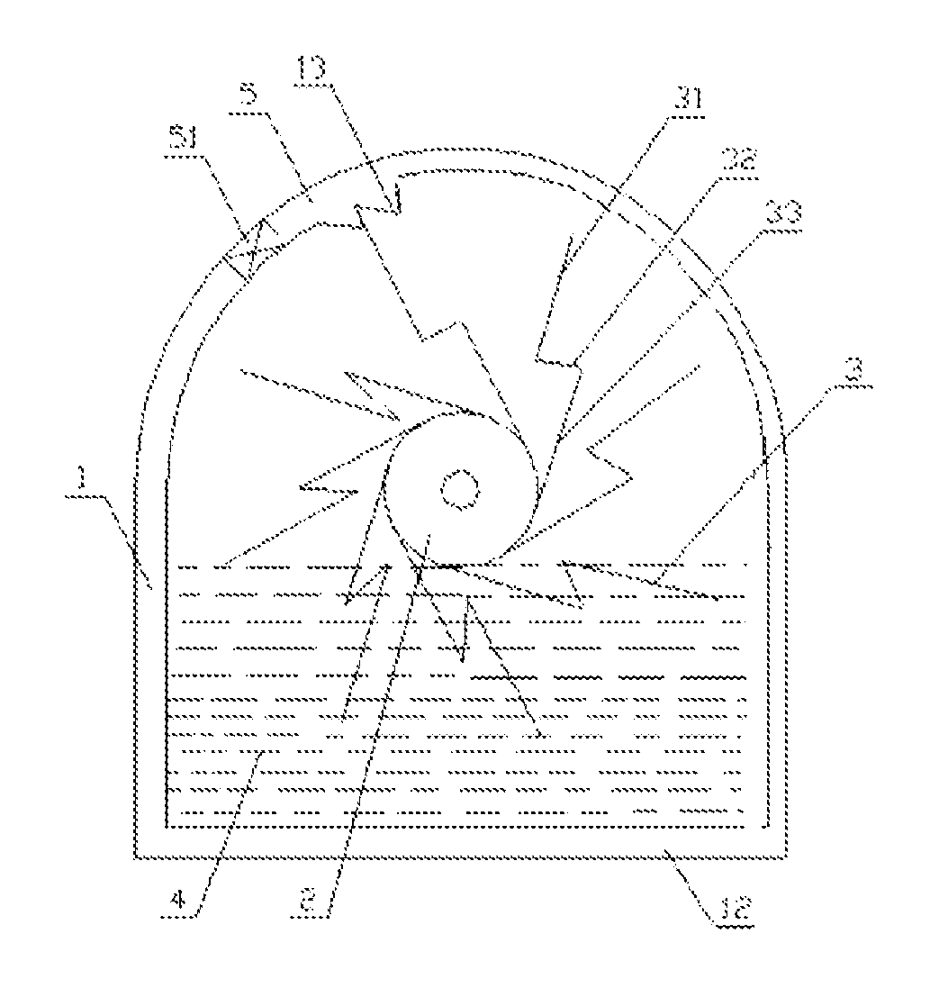
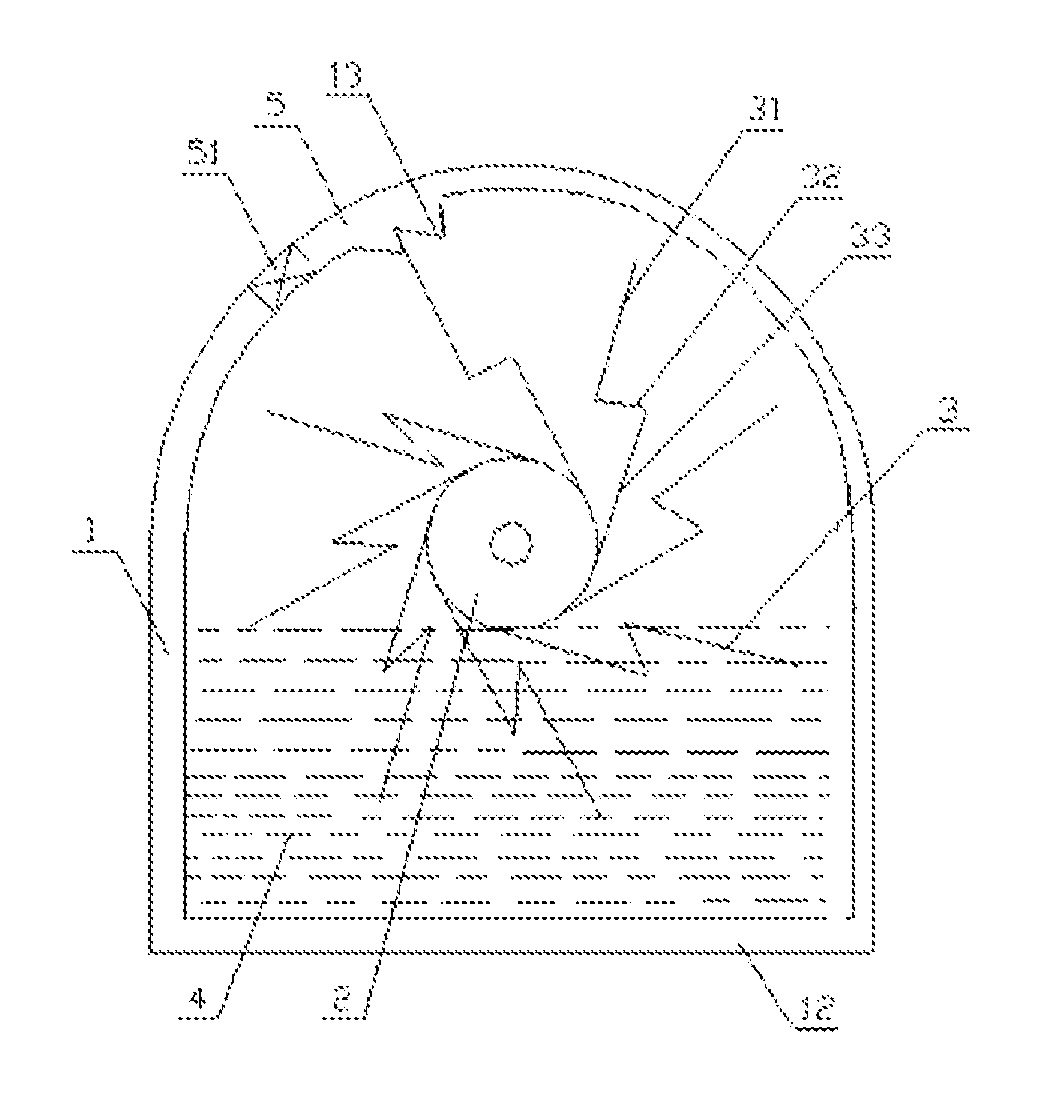
[0020]A solar-powered apparatus, as shown in FIG. 1, comprises a housing 1, a shield panel 5 disposed on the housing 1, and a transmission apparatus 2 disposed inside the housing 1, the transmission apparatus 2 is provided with eight alloy sheets 3, and the housing 1 is further provided with a ratchet pawl 13; and the shield panel 5 is provided with a light-focusing apparatus 51 for focusing light. The housing 1 is provided with a ratchet pawl 13 having a locking function, so the alloy sheets 3 are capable of rotating clockwise only. When stretching after heated via the light-focusing apparatus 51, the alloy sheets 3 drive the transmission apparatus 2 to rotate clockwise. When rotating clockwise, the transmission apparatus 2 may also drive the alloy sheets 3 disposed on the transmission apparatus 2 to rotate clockwise synchronously. In this way, the whole solar-powered apparatus rotates.

[0021]Each of the alloy sheets 3 is a panel bent by rotating anticlockwise by 120° to form a...

embodiment 2

[0028

[0029]A solar-powered apparatus, as shown in FIG. 1, comprises a housing 1, a shield panel 5 disposed on the housing 1, and a transmission apparatus 2 disposed inside the housing 1, the transmission apparatus 2 is provided with sixteen alloy sheets 3, and the housing 1 is further provided with a ratchet pawl 13; and the shield panel 5 is provided with a light-focusing apparatus 51 for focusing light. The housing 1 is provided with a ratchet pawl 13 having a locking function, and so the alloy sheets 3 are capable of rotating clockwise only. When stretching after heated via the light-focusing apparatus 51, the alloy sheets 3 drive the transmission apparatus 2 to rotate clockwise. When rotating clockwise, the transmission apparatus 2 may also drive the alloy sheets 3 disposed on the transmission apparatus 2 to rotate clockwise together. In this way, the whole solar-powered apparatus rotates.

[0030]Each of the alloy sheets 3 is a panel bent by rotating anticlockwise by 160° to form ...


PUM


Abstract

The invention relates to a solar-powered apparatus, comprising a housing (1), a shield panel (5) disposed on the housing (1), and a transmission apparatus (2) disposed inside the housing (1). The transmission apparatus (2) is provided with eight or more memory alloy sheets (3). The housing (1) is also provided with a ratchet pawl (13). The shield panel (5) is provided with a light-focusing apparatus (51) used for focusing light. The apparatus is capable of converting solar energy into mechanical energy.

Description

TECHNICAL FIELD OF THE INVENTION[0001]The invention relates to an apparatus for converting solar energy into kinetic energy, and in particular, to a solar-powered apparatus.BACKGROUND OF THE INVENTION[0002]With the development of the world economy, the consumption of energy increases greatly. For the moment, because of the serious imbalance between supply and demand, the price of energy, mainly petroleum, has surged, which affects and involves the economic development around the world, and brings extreme risk for worldwide economic development. Therefore, people become committed to developing and utilizing new energy. As a new kind of clean and renewable energy, solar energy has been receiving more and more recognition.SUMMARY OF THE INVENTION[0003]In view of the defects in the prior art that traditional energy like petroleum is in shortage and has seriously environmental pollution, and the utilization rate of solar energy in a unit area for common solar energy installations is low,...

Claims


Application Information

Patent Timeline
Patent Type & Authority Patents(United States)
IPC IPC(8): F03G7/06F03G6/00
CPCF03G7/065F03G6/00Y02E10/46F03G6/002
Inventor LI, TONGQIANGJIANG, XIAONING
Owner ZHEJIANG GONGSHANG UNIVERSITY
Learn More