Radiation image detecting device and radiation imaging system

a radiation image and detection device technology, applied in the field of radiation image detection devices and radiation imaging systems, can solve the problems of reducing the image quality of the x-ray image, requiring time and effort to obtain the gain image, and causing the image quality to be degraded. , to achieve the effect of reducing the fear of image quality degradation and requiring no time and effor

Active Publication Date: 2017-02-28
FUJIFILM CORP
View PDF5 Cites 10 Cited by
  • Summary
  • Abstract
  • Description
  • Claims
  • Application Information

AI Technical Summary

Benefits of technology

[0020]An object of the present invention is to provide a radiation image detecting device and a radiation imaging system that can perform stable AEC that is insusceptible to misalignment in geometrical disposition between a grid and dose detection sensors with having little fear of degradation in image quality and requiring no time and effort.
[0030]According to the present invention, the arrangement period of the plurality of dose detection sensors disposed in the imaging surface with leaving space is different from the arrangement period of the radiation absorbing portions in the grid. Accordingly, not all of the plurality of dose detection sensors is situated behind the radiation transmitting portions or the radiation absorbing portions. Therefore, it is possible to perform the stable AEC that is insusceptible to misalignment in the geometrical disposition between the grid and the dose detection sensors with having little fear of degradation in the image quality and requiring no time and effort.

Problems solved by technology

In other words, since the dose detection sensors are disposed in the imaging surface, the misalignment occurs in the geometrical disposition between the grid and the dose detection sensors owing to an attachment backlash of the grid, a manufacturing error of the grid, and the like.
Thus, the attachment backlash or the manufacturing error of the grid easily causes the misalignment of the order of one X-ray absorbing portion or one X-ray transmitting portion between the grid and the dose detection sensors.
Even if the type of the grid and the imaging condition are the same, an attachment backlash of the grid or a manufacturing error causes misalignment in the geometrical disposition between the grid and the detection pixels, so that the gain image is obtained whenever imaging is carried out.
Thus, it is difficult to completely eliminate the defect by the defect correction to the extent of being invisible, and it is feared that the image quality of the X-ray image may be degraded.
However, in the case of the X-ray image detecting device described in the U.S. Pat. No. 6,944,266, the gain image has to be obtained whenever imaging is carried out, and hence there is another problem that obtaining the gain image requires time and effort.
Furthermore, if the geometrical disposition between the grid and the detection pixels is misaligned after obtainment of the gain image and before carrying out actual imaging, the correction cannot be performed appropriately with the obtained gain image.

Method used


Image

  • Radiation image detecting device and radiation imaging system
  • Radiation image detecting device and radiation imaging system
  • Radiation image detecting device and radiation imaging system

Examples


first embodiment

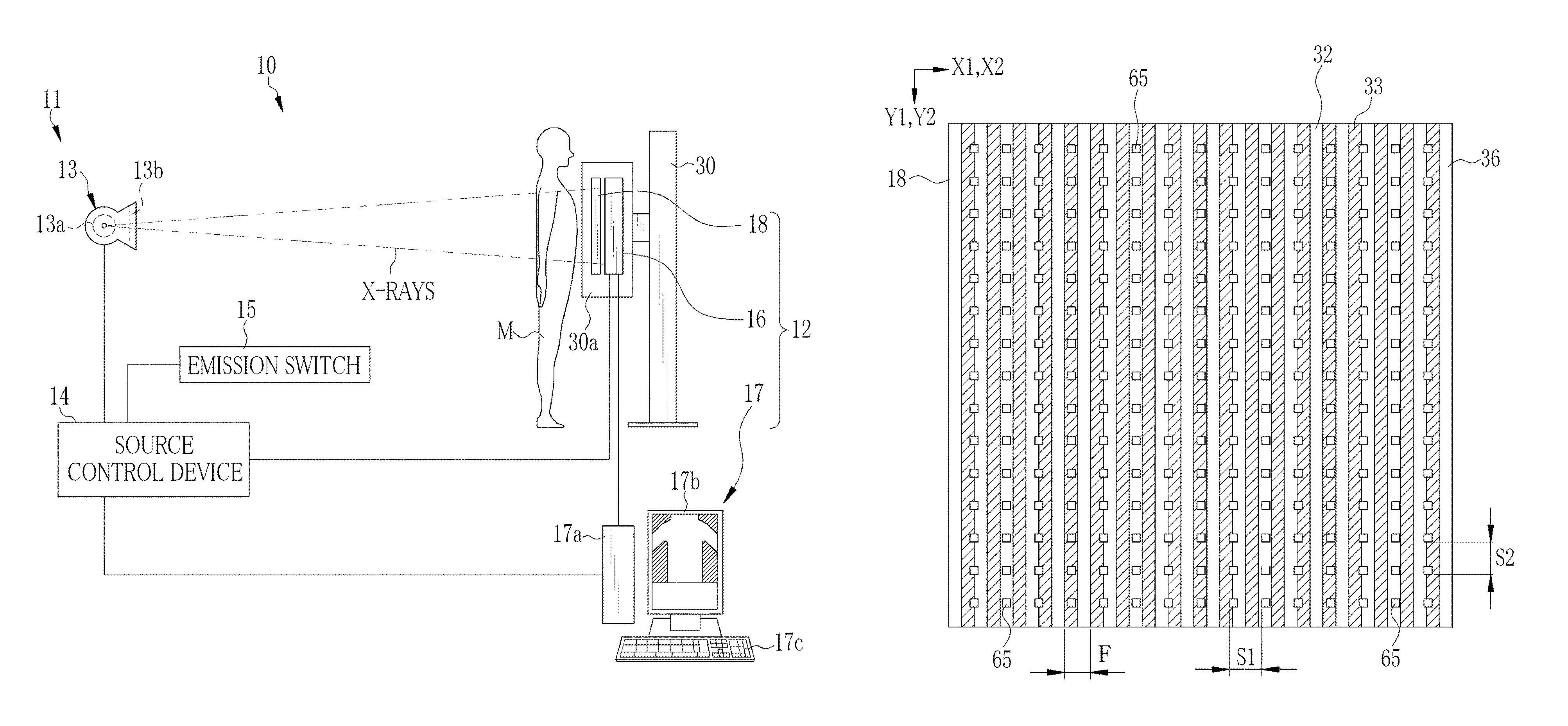
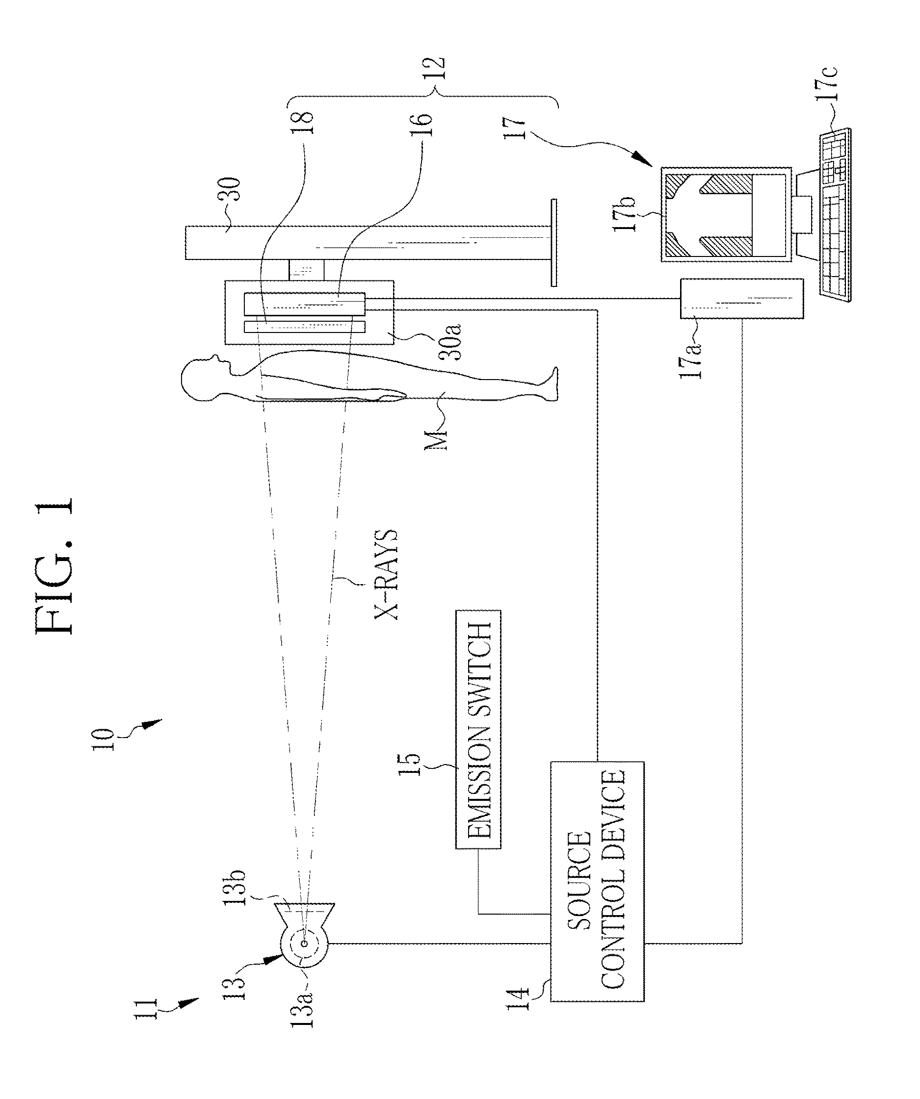
[0059]As shown in FIG. 1, an X-ray imaging system 10 according to the present invention is constituted of an X-ray generating device 11 for generating X-rays and an X-ray imaging device 12 for taking an X-ray image from the X-rays passed through a patient M, being an object. The X-ray generating device 11 includes an X-ray source 13 for emitting the X-rays, a source control device 14 for controlling the X-ray source 13, and an emission switch 15 for commanding the start of X-ray emission. The X-ray imaging device 12 includes an electronic cassette 16 being a portable X-ray image detecting device, a console 17 for controlling the electronic cassette 16, and an imaging stand 30. The source control device 14, the electronic cassette 16, and the console 17 are connected wiredly or wirelessly so as to be communicated with each other. An upright type imaging stand is used as the imaging stand 30 in this embodiment, but a bed type imaging stand may be used instead.

[0060]The electronic cass...

second embodiment

[0137]In a second embodiment shown in FIGS. 18 and 19, each of the arrangement period S1 and the arrangement period F is represented as a length in unit of the number of the pixels 45. In FIG. 18, the arrangement period S1 is 7 because there is space of six pixels 45 between the two detection pixels 65. The arrangement period F has a length of four pixels 45, so a conversion value, being the number of pixels 45 into which the arrangement period F is converted, is 4. In an example shown in FIG. 19, the arrangement period S1 is 6, and the arrangement period F is 4.

[0138]Both of FIGS. 18 and 19 satisfy the relation of arrangement period S1≠the arrangement period F, and hence represent embodiments included in the present invention. However, comparing between FIGS. 18 and 19, an example of FIG. 18 is more preferable. The reason is as follows. In the example of FIG. 18, since the arrangement period S1 of the detection pixels 65 is 7 and the arrangement period F is 4, the arrangement perio...

third embodiment

[0144]In a third embodiment shown in FIGS. 20 to 22, an array of the detection pixels 65 in which the average of the dose detection signals of the detection pixels 65 is calculated is grouped into one set 200. The sets 200 are periodically arranged in the same or different rows, so as to arrange the sets 200 over the entire imaging surface 36 in a distributed manner. The set 200 is a minimum unit of a group of the detection pixels 65 in which the AEC section 67 calculates the average of the dose detection signals. Note that, the sets 200 may be arranged intensively in a region corresponding to the measurement area set in advance, such as left and right lung fields, for example, instead of being arranged over the entire imaging surface 36.

[0145]A set 200a shown in FIG. 20A is an example in which a plurality of detection pixels 65 (four detection pixels 65 in this example) is arrayed in one row extending in the X2 direction at an arrangement period S1=5, and the sets 200a are regularl...


PUM


Abstract

A detection panel has a plurality of pixels for accumulating electric charge by receiving X-rays, and a plurality of detection pixels for detecting an X-ray dose in an imaging surface. The detection pixels are disposed periodically with leaving space. A grid, which has X-ray absorbing portions and X-ray transmitting portions alternately and periodically arranged in a first direction, is disposed in a position opposed to the imaging surface. Since an arrangement period of the detection pixels in the first direction is different from an arrangement period of the X-ray absorbing portions, an output value of each detection pixel is distributed and hence the average of the output values has a reduced variation range.

Description

CROSS-REFERENCE TO RELATED APPLICATIONS[0001]This application is a continuation of PCT International Application No. PCT / JP2013 / 060921 filed on Apr. 11, 2013, which claims priority under 35 U.S.C. 35 §119(a) to Japanese Patent Application No. 2012-096277 filed on Apr. 20, 2012. Each of the above applications is hereby expressly incorporated by reference, in its entirety, into the present application.BACKGROUND OF THE INVENTION[0002]1. Field of the Invention[0003]The present invention relates to a radiation image detecting device having a dose detection sensor for performing exposure control of a radiographic image, and a radiation imaging system using the radiation image detecting device.[0004]2. Description Related to the Prior Art[0005]In a medical field, a radiation imaging system, for example, an X-ray imaging system using X-rays as a kind of radiation is known. The X-ray imaging system is constituted of an X-ray generating device for producing the X-rays, and an X-ray imaging d...

Claims


Application Information

Patent Timeline
Patent Type & Authority Patents(United States)
IPC IPC(8): H05G1/42A61B6/00H05G1/44G21K1/02
CPCA61B6/4291A61B6/4208A61B6/4283A61B6/542H05G1/44G21K1/02
Inventor TAJIMA, TAKASHIKUWABARA, TAKESHIKITAGAWA, YUSUKE
Owner FUJIFILM CORP
Why Eureka
Try Eureka