Transparent polyurethane protective coating, film and laminate compositions with enhanced electrostatic dissipation capability, and methods for making same

a technology of transparent polyurethane and composition, applied in the direction of paper/cardboard containers, instruments, conductive layers on insulating supports, etc., can solve the problems of transient charge transfer to the surface via triboelectric, several serious problems affecting aircraft performance, and safety, and achieve the effect of enhancing the service life and safety of transparent polyurethane compositions

Active Publication Date: 2017-02-28
GKN AEROSPACE TRANSPARENCY SYST
View PDF18 Cites 7 Cited by
  • Summary
  • Abstract
  • Description
  • Claims
  • Application Information

AI Technical Summary

Benefits of technology

[0016]In another embodiment, the middle conductive material layer is formed as a mesh or porous network that allows the outer polyurethane layer to interact and bond with the inner polyurethane layer through the porous network. The interaction of the inner and outer polyurethane layers allows the transparent polyurethane laminate to behave substantially like a single, thick polyurethane layer with regard to abrasion and erosion resistance.

Problems solved by technology

This charging is caused by contact with ice crystals and other particles during flight, which results in transfer of a charge to the surface via triboelectric or frictional effects.
P-static charging of a non-conductive (dielectric) outer surface can create several serious problems affecting aircraft performance, transparency service life, and safety.
Discharge during flight can result in damage to outer coating layers from dielectric breakdown or can result in electronic interference with instruments.
Such charge accumulation can also create shock hazards for flight and ground personnel.
Polyurethanes and other organic polymers generally are poor conductors of electricity.
Consequently, these polymers cannot be used satisfactorily without modification in applications where static dissipative properties are required.
This method is not suitable for use with polyurethanes that are transparent, however, because the conductive filler materials are opaque and greatly reduce the light transmission of the modified material.
Again, however, this method is not suitable for use with polyurethanes that are transparent, because the conductive polymer additives form a dispersed phase that reduces transparency.
In addition, polyanilines, polythiophenes and other conductive polymers do not have good environmental stability and generally cause reduction in overall resistance to weathering and environmental degradation.
This method is not suitable for polyurethane coatings and laminates, however, because the additive also migrates to the surface of the polyurethane that interfaces with the underlying substrate, resulting in a loss of adhesion.
In addition, such additives can lose their effectiveness over time, because they can leach from the polyurethane under normal use conditions.
In general, non-ionic additives and polyol modifiers have been found to significantly enhance electrical conductivity only if used at high levels, which can adversely affect other important properties, such as transparency and mechanical strength.
However, none of these ionic additives is considered fully satisfactory for use in transparent polyurethanes used as coatings or in laminates, because they are fugitive and with aging they can cause a loss of transparency and a loss of adhesion.
None of these known additives for increasing the electrical conductivity of polyurethanes is considered fully satisfactory for use in polyurethanes that are transparent, and particularly in polyurethanes that are used as coatings or in laminates for aircraft windows.
All prior art modification methods used to enhance conductivity of thick polyurethane coatings and films suffer from one limitation: Conductivity is strongly dependent on temperature.

Method used


Image

  • Transparent polyurethane protective coating, film and laminate compositions with enhanced electrostatic dissipation capability, and methods for making same
  • Transparent polyurethane protective coating, film and laminate compositions with enhanced electrostatic dissipation capability, and methods for making same
  • Transparent polyurethane protective coating, film and laminate compositions with enhanced electrostatic dissipation capability, and methods for making same

Examples


examples 1-3

[0047]In examples 1-3, three polyurethane protective coatings were prepared as described in U.S. Pat. No. 6,458,875 to Sandlin et al., Example 15. A transparent aliphatic polyesterurethane mix, suitable for coating, laminating or casting, was prepared from the formulation set forth in Table 4 below.

[0048]

TABLE 4Aliphatic Polyesterurethane Formulation for Examples 1-3Raw MaterialDescriptionParts (wt. %)Desmodur W1Bis(4-isocyanato-38.21cyclohexyl)methaneCAPA 30502Polycaprolactone triol43.42CAPA 20852Polycaprolactone diol17.01ButanediolChain extender0.36Tinuvin 3283UV stabilizer0.50Irganox 10103Antioxidant0.501Available from Bayer2Available from Perstop Specialty Chemicals3Available from Ciba-Geigy

[0049]After a homogeneous solution of the specified polyesterurethane mix was prepared, with the solution temperature at 100° F., 30 ppm dibutyl tin dilaurate catalyst and an antistatic additive were added. The antistatic additive was Fluorad HQ115, a lithium trifluoro-methanesulfonimide avai...

example 4

[0057]In example 4, a polyurethane coating was prepared from the components set forth in Table 7 below.

[0058]

TABLE 7Aliphatic Polyesterurethane Formulation for Example 4Raw MaterialDescriptionParts (wt. %)Desmodur W1Bis(4-isocyanato-39.5cyclohexyl)methaneCAPA 30502Polycaprolactone triol33.8CAPA 20852Polycaprolactone diol25.7Tinuvin 3283UV stabilizer0.5Irganox 10103Antioxidant0.51Available from Bayer2Available from Perstop Specialty Chemicals3Available from Ciba-Geigy

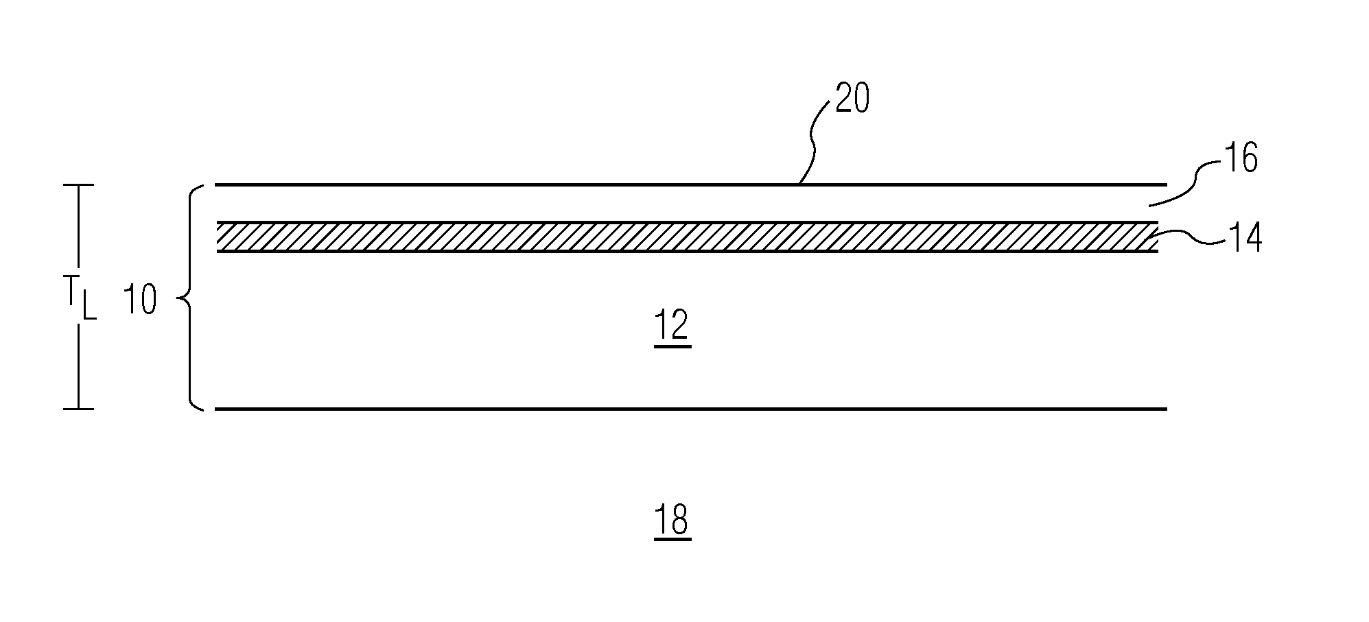
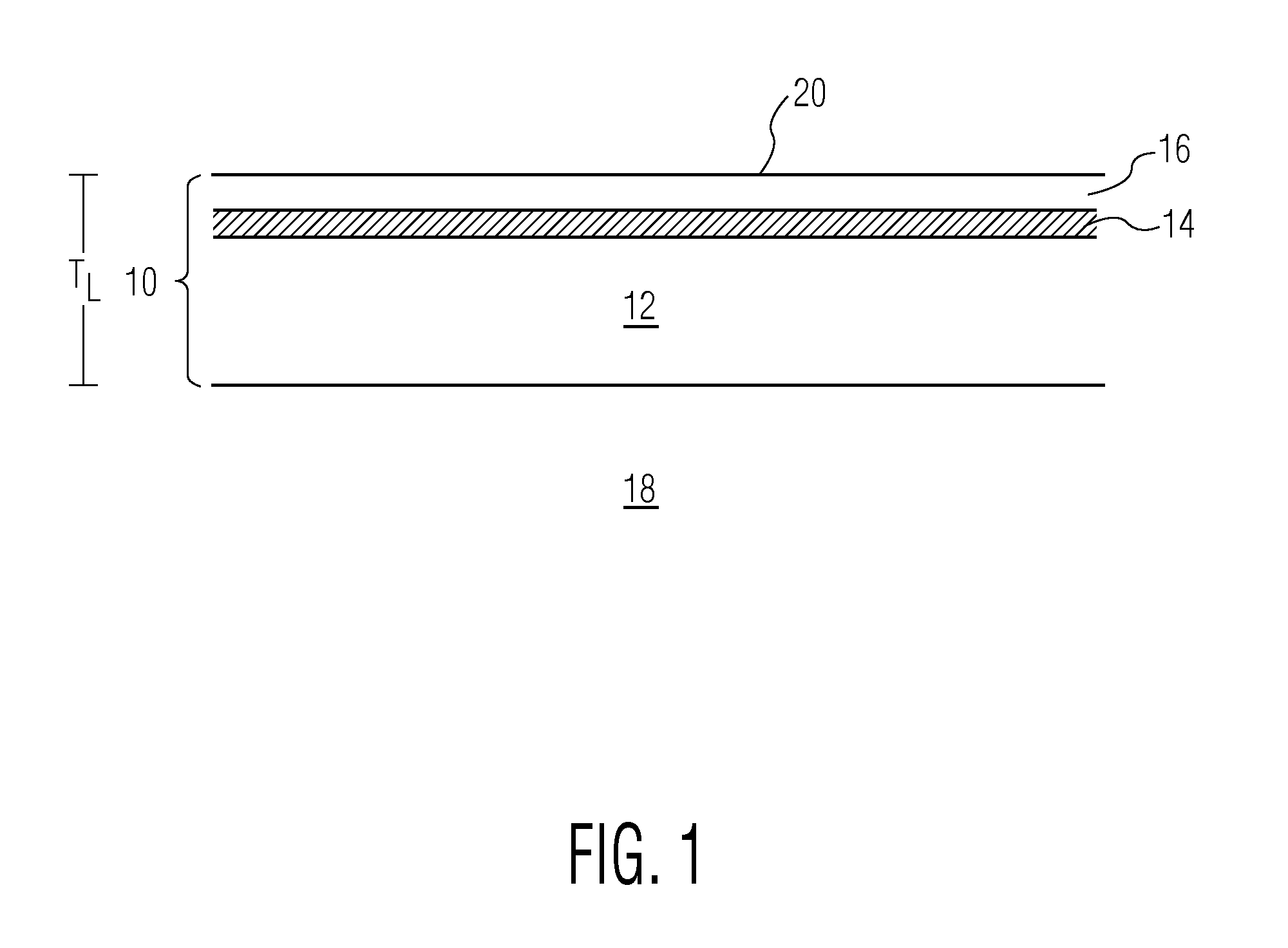
[0059]The coating solution of Example 4 was prepared by adding dipropylene glycol dimethyl ether to the formulation of Table 7 to give a 90-percent solids solution. The coating was applied over a conductive coated polycarbonate panel prepared per Tables 1-3. The polyurethane coating was cured at 120° F. for 12 hours followed by 250° F. for 18 hours. Polyurethane coating thickness was 0.003 inches (75 μ).

example 5

[0060]Example 5 comprised two coating solutions, an inner coating solution and an outer coating solution, each having the same polyurethane composition as in Example 4. The solvents and final solids contents were as shown in Table 8.

[0061]

TABLE 8Solvents and Final Solids Contents for Example 5Inner coatingDipropylene glycol dimethyl ether, 70%Outer coating2-Butoxyethyl acetate, 45%

[0062]The inner coating was flow coated directly onto a polycarbonate sheet having no conductive coating. The coating was cured for 12 hours at 120° F. followed by 18 hours at 250° F. The coating thickness was 0.0025 inch (63 μ).

[0063]A conductive ITO / silicate coating prepared according to Tables 1-3 was applied over the inner polyurethane coating. The conductive coating was cured at 250° F. for 1 hour.

[0064]The outer coating of Table 8 was then applied over the ITO / silicate coating and cured at 250° F. for 18 hours. The thickness of the outer coating was 0.0005 inch (13 μ).

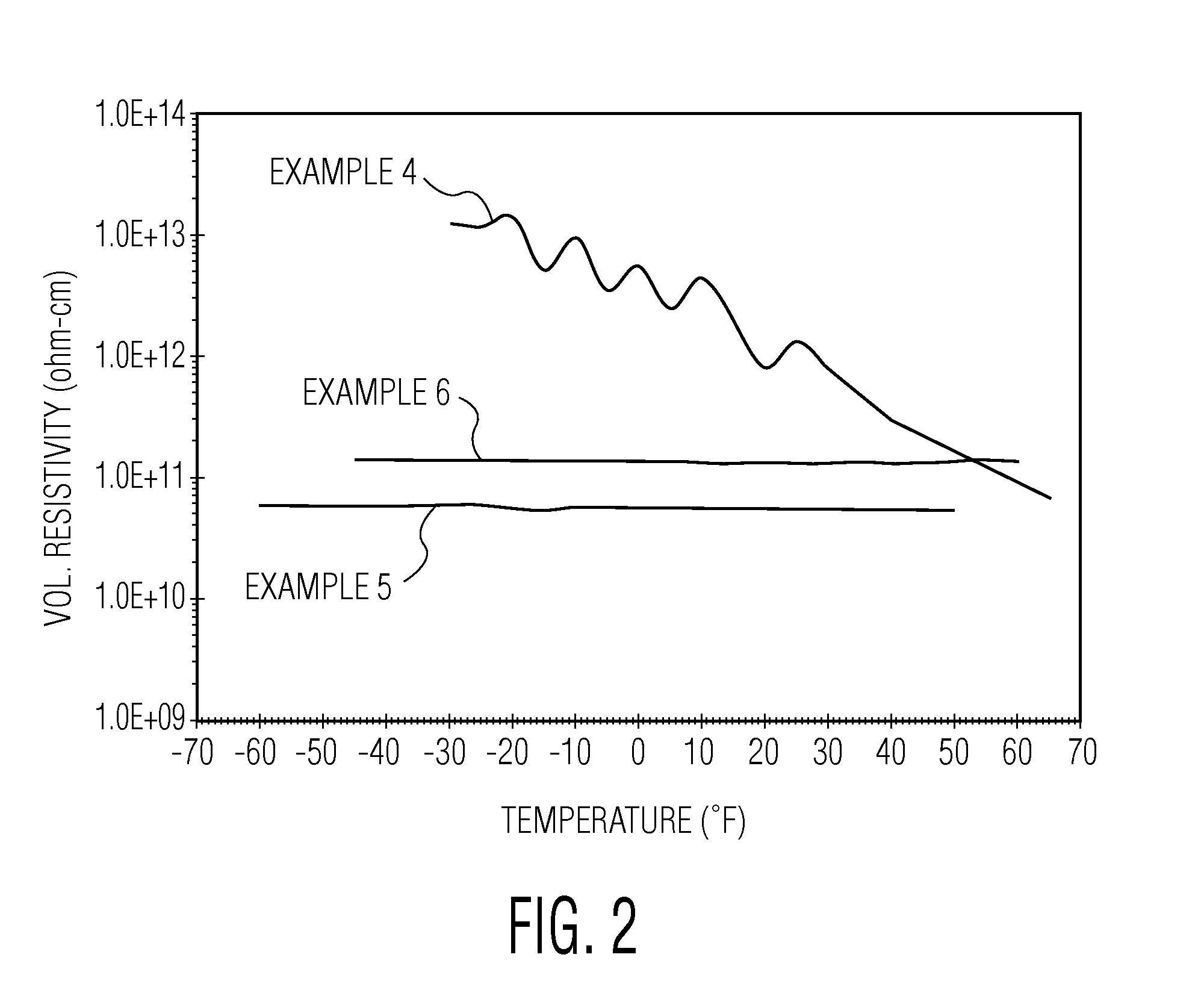
[0065]The ability to drain surfa...


PUM

PropertyMeasurementUnit
thickaaaaaaaaaa
thickaaaaaaaaaa
applied voltageaaaaaaaaaa

Abstract

The present invention is embodied in a transparent, polyurethane laminate or multi-layer coating comprising a first transparent polyurethane layer, a middle conductive material layer disposed on the first transparent polyurethane layer, and a second transparent polyurethane layer disposed on the conductive layer. In one embodiment, the subject invention addresses the problem of static charge buildup on aircraft transparencies by allowing charge to drain through the second transparent polyurethane layer to the conductive material layer and then to the edge of the conductive material layer, where it is mated to the airframe. The present invention is also embodied in a method for forming a transparent polyurethane laminate on a transparent substrate and a method for forming a free-standing laminate.

Description

BACKGROUND OF THE INVENTION[0001]The present invention relates generally to transparent polyurethane compositions, and to coated and laminated aircraft transparencies incorporating such compositions, and more particularly to such compositions, coated transparencies, and laminates having antistatic or static dissipative properties.[0002]Transparencies used for modern military aircraft often require a protective, erosion-resistant coating or film located on the outer surface. Such protective outer layers are required to prevent damage to fragile underlying metal or ceramic conductive coatings, such as gold or indium tin oxide (ITO), or to protect a plastic surface having limited environmental durability, such as polycarbonate. Transparent polyurethane coatings and films are preferred for these applications due to their superior erosion resistance properties, excellent transparency and good environmental durability.[0003]The outer surface of an aircraft transparency is subject to elect...

Claims


Application Information

Patent Timeline
Patent Type & Authority Patents(United States)
IPC IPC(8): B32B27/40C08J5/12B32B5/18B32B37/14B32B37/02B32B27/08B32B27/36B64C1/14
CPCC08J5/12B32B27/08B32B27/365B32B27/40B64C1/1484B32B2255/10B32B2255/20B32B2255/205B32B2307/202B32B2307/21B32B2307/412B32B2605/18B64C1/1492C08J2375/04Y10T156/10Y10T428/265Y10T428/31554Y10T428/31598Y10T428/31609B32B5/18B32B27/06H01B5/14
Inventor MONCUR, MARLOWEHOO, LINSANDLIN, STEPHEN
Owner GKN AEROSPACE TRANSPARENCY SYST
Why Eureka
Try Eureka