Method and apparatus for processing coded aperture radar (CAR) signals

a technology of aperture radar and coded aperture, applied in the direction of reradiation, measurement devices, instruments, etc., can solve the problems of significant computation, no known prior art for processing methods and hardware for car signals, and often prohibitive amount of memory

Active Publication Date: 2017-02-28
HRL LAB
View PDF30 Cites 4 Cited by
  • Summary
  • Abstract
  • Description
  • Claims
  • Application Information

AI Technical Summary

Problems solved by technology

CAR is a new technology that has not yet been implemented in IC form, therefore is no known prior art for processing methods and hardware for CAR signals.
This technique is effective, but requires an often prohibitive amount of memory to store the reference signals, and significant computation to perform the correlations in a CPU (for example).
This is highly computationally intensive and introduces significant latency for large arrays due to the limited speed with which basic digital calculations (e.g., multiplications) may be made.
However, the fact that digital beamforming combines signals from all the elements creates highly complex combining networks that quickly become unfeasible as the array gets large and even more particularly so if the array is a two dimensional (2D) array.

Method used


Image

  • Method and apparatus for processing coded aperture radar (CAR) signals
  • Method and apparatus for processing coded aperture radar (CAR) signals
  • Method and apparatus for processing coded aperture radar (CAR) signals

Examples


Embodiment Construction

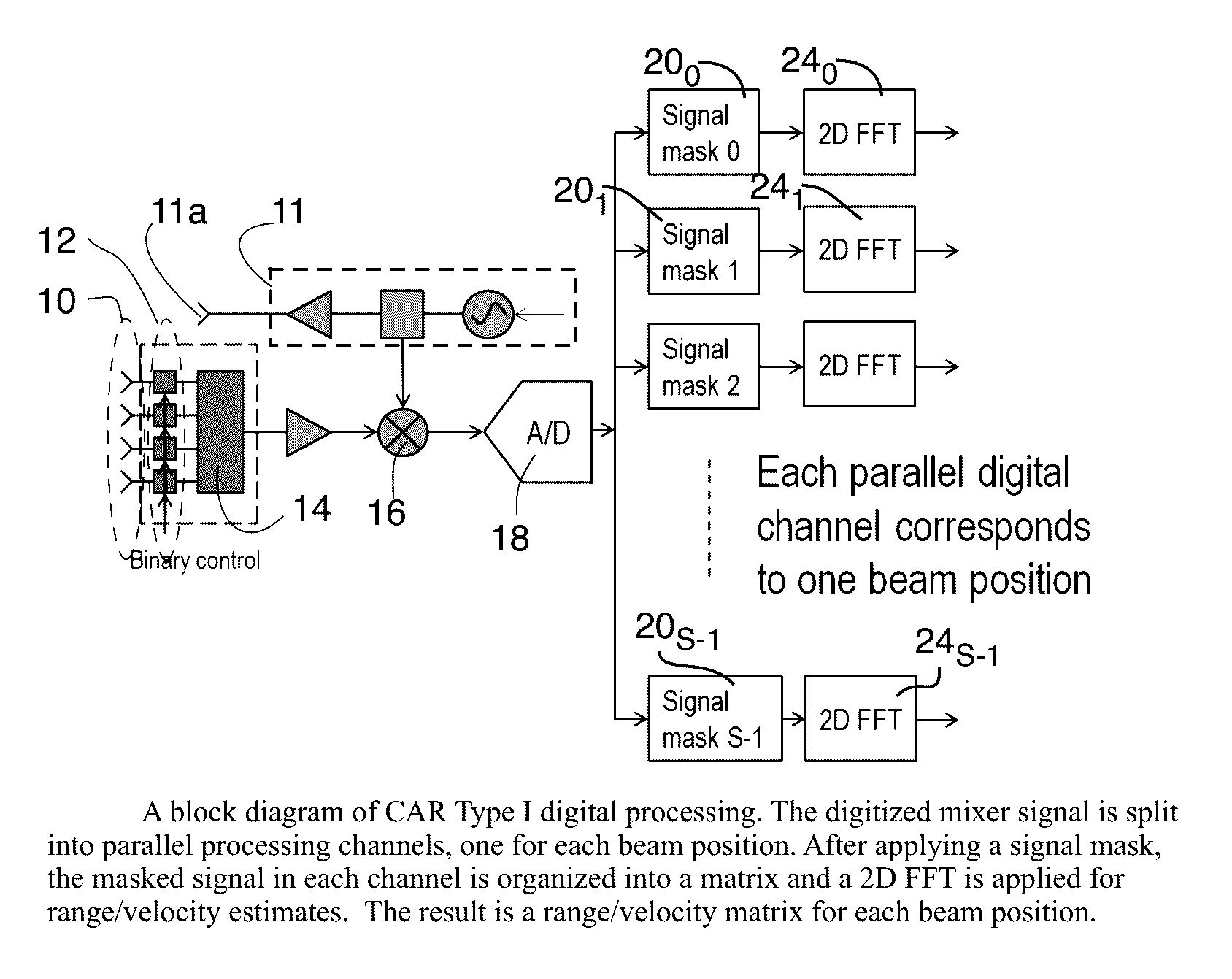
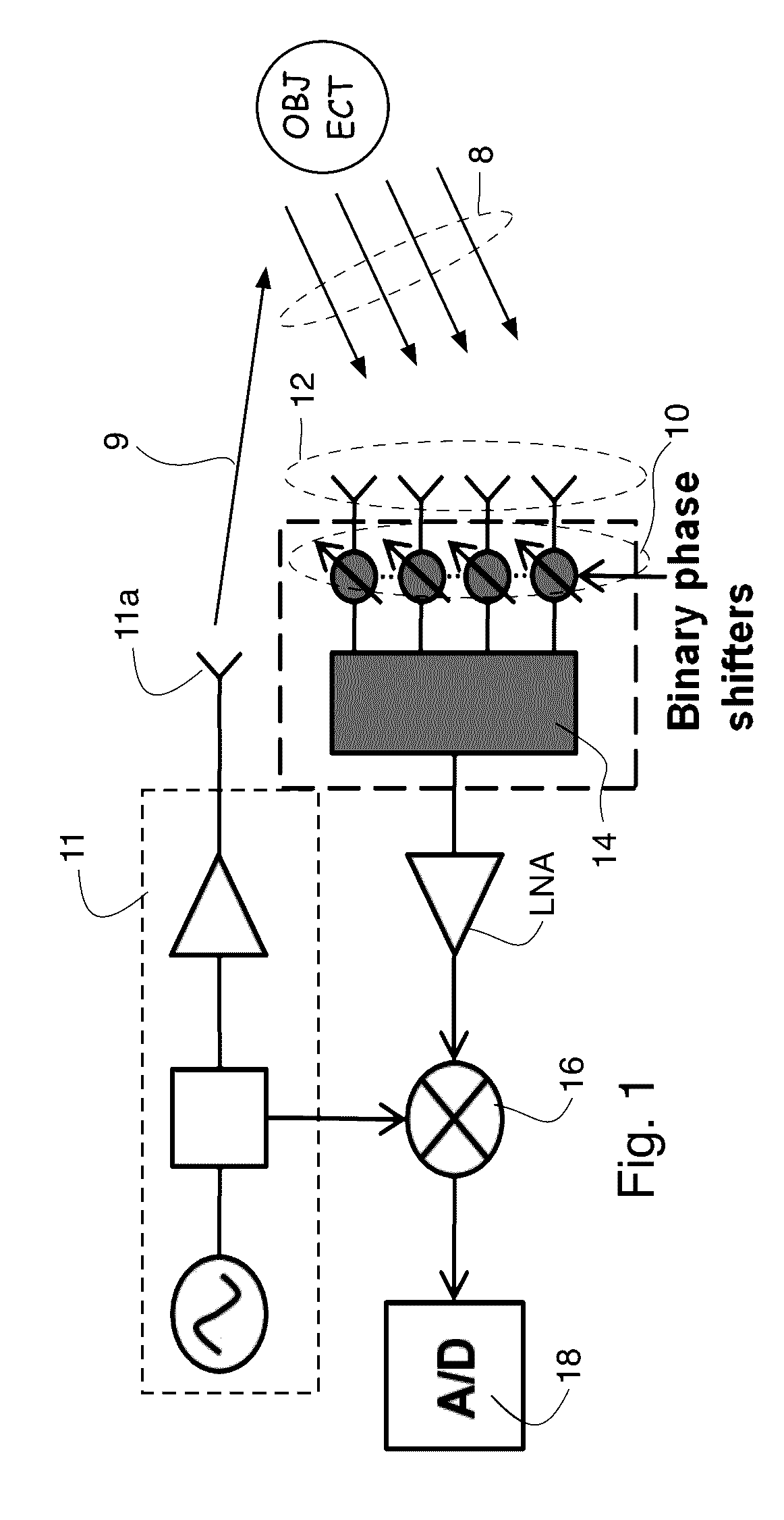
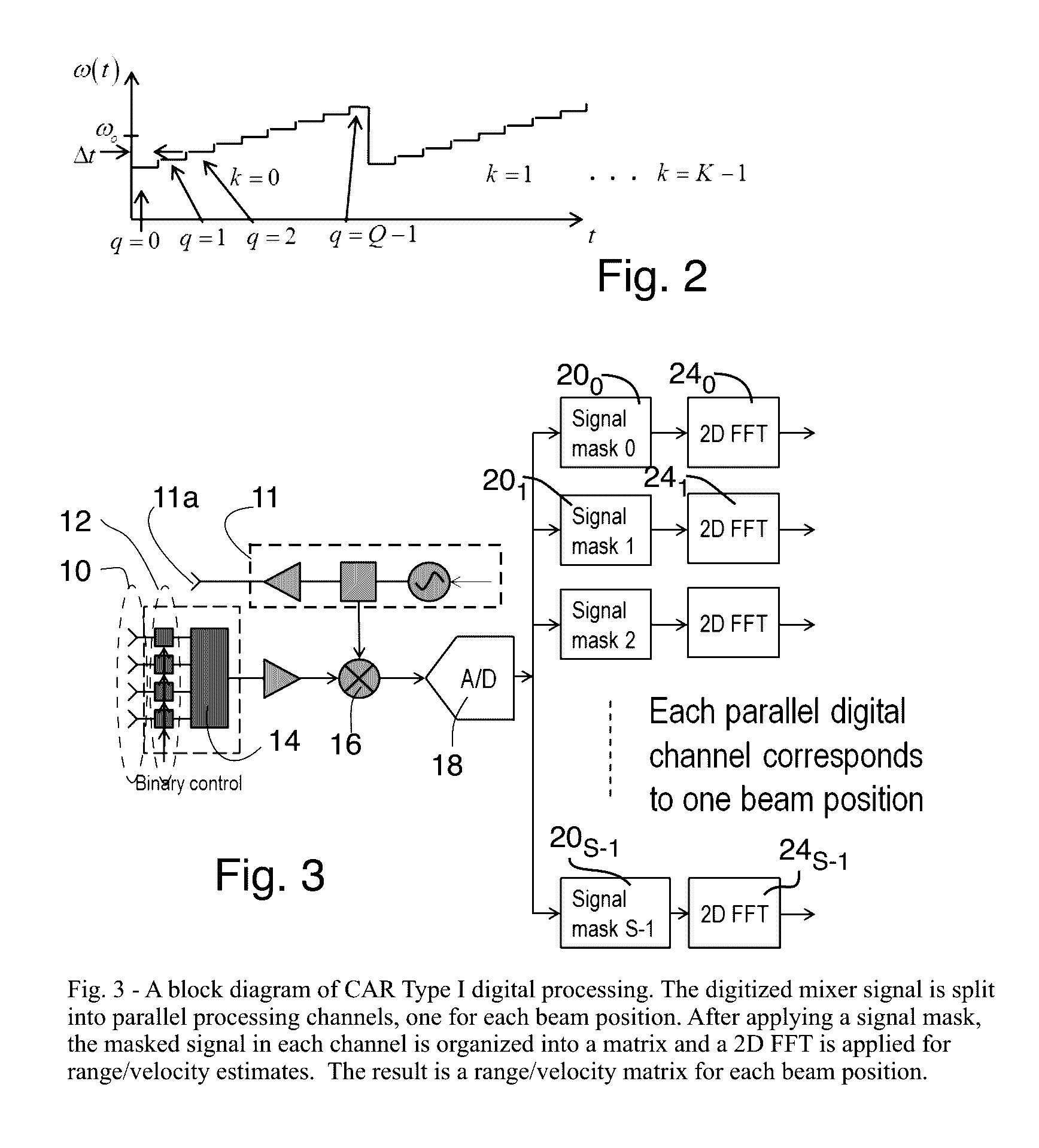
[0022]FIG. 1 shows a block diagram of CAR, with CAR coding on receive only which simplifies the hardware which is utilized. A radar signal 9 is transmitted from an antenna element 11a associated with a radar transmitter 11. The transmitted signal 9 covers a field of view (FOV) and energy is scattered from one or more objects within the FOV, which scattered energy 8 is received by an array of receiving radar antenna elements 12 associated with a radar receiver. In some embodiments, antenna elements may be shared by both the radar transmitter and the radar receiver (with appropriate switching to isolate the receiver from the relatively high energy signal which is typically transmitted by the transmitter to keep from damaging the receiver by that high energy signal). The array of receiving radar antenna elements 12, in practice, is preferably a two dimensional array, but a one dimensional array is more convenient for analysis and simulation and may be used in practice.

[0023]Each of the...


PUM


Abstract

A radar system in which Coded Aperture Radar processing is performed on received radar signals reflected by one or more objects in a field of view which reflect a transmitted signal which covers a field of view with K sweeps and each sweep including Q frequency changes. For Type II CAR, the transmitted signal also includes N modulated codes per frequency step. The received radar signals are modulated by a plurality of binary modulators the results of which are applied to a mixer. The output of the mixer, for one acquisition results in a set of Q·K (for Type I CAR) or Q·K·N (for Type II CAR) complex data samples, is distributed among a number of digital channels, each corresponding to a desired beam direction. For each channel, the complex digital samples are multiplied, sample by sample, by a complex signal mask that is different for each channel.

Description

CROSS REFERENCE TO RELATED APPLICATIONS[0001]This application claims priority to and the benefit of U.S. Provisional Patent Application Ser. No. 61 / 912,990, filed Dec. 6, 2013 and entitled “A Method and Apparatus for Processing Coded Aperture Radar Signals”. The disclosure of that U.S. Provisional Patent Application Ser. No. 61 / 912,990, is hereby incorporated herein by this reference.[0002]This application is related to U.S. patent application Ser. No. 13 / 490,607 filed Jun. 7, 2012 and entitled “Coded Aperture Beam Analysis Method and Apparatus”, the disclosure of which is hereby incorporated herein by reference.[0003]This application is also related to U.S. patent application Ser. No. 13 / 725,621, filed Dec. 21, 2012 and entitled “Coded Aperture Beam Analysis Method and Apparatus”, the disclosure of which is hereby incorporated herein by reference.[0004]This application is also related to U.S. patent application Ser. No. 14 / 561,142 filed on the same date as this application, Dec. 4,...

Claims


Application Information

Patent Timeline
Patent Type & Authority Patents(United States)
IPC IPC(8): G01S13/72G01S7/28G01S13/536G01S13/02G01S7/02G01S13/34G01S13/44G01S13/94G01S13/88G01S7/35G01S13/93G01S13/931G01S13/935
CPCG01S7/2813G01S7/02G01S13/02G01S13/343G01S13/4418G01S13/4463G01S13/536G01S13/882G01S13/931G01S13/94G01S2007/356G01S13/935G01S7/356
Inventor LYNCH, JONATHAN J.XU, ZHIWEI A.KUAN, YEN-CHENG
Owner HRL LAB
Why Eureka
Try Eureka