Method and system for image correction using a quasiperiodic grid

a quasi-periodic grid and image correction technology, applied in image enhancement, image analysis, instruments, etc., can solve problems such as difficult correction, chromatic aberration, and complicated registration tasks, and achieve the effect of correcting image distortion

Active Publication Date: 2017-02-28
PERKINELMER CELLULAR TECH GERMANY GMBH
View PDF13 Cites 4 Cited by
  • Summary
  • Abstract
  • Description
  • Claims
  • Application Information

AI Technical Summary

Benefits of technology

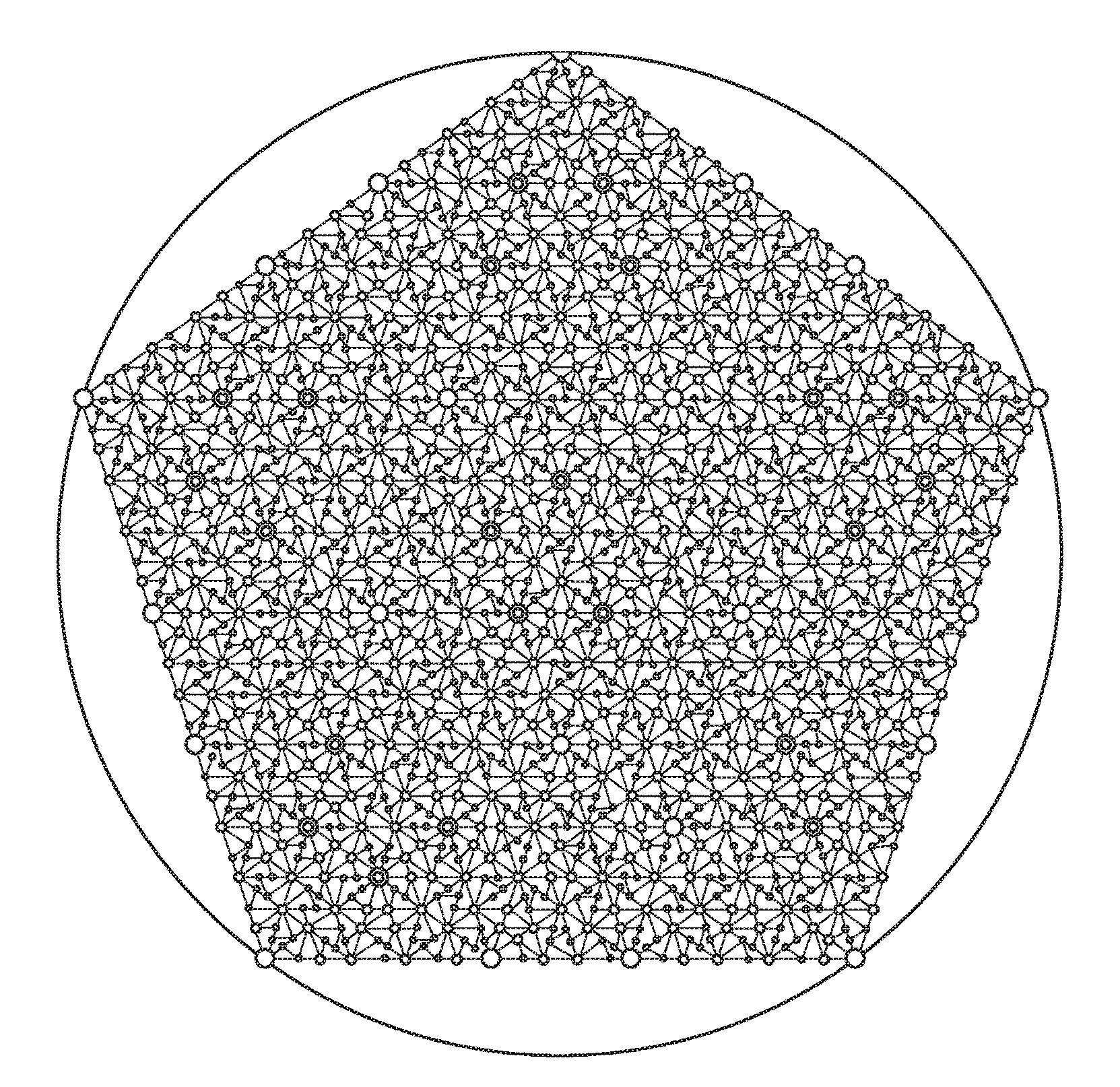
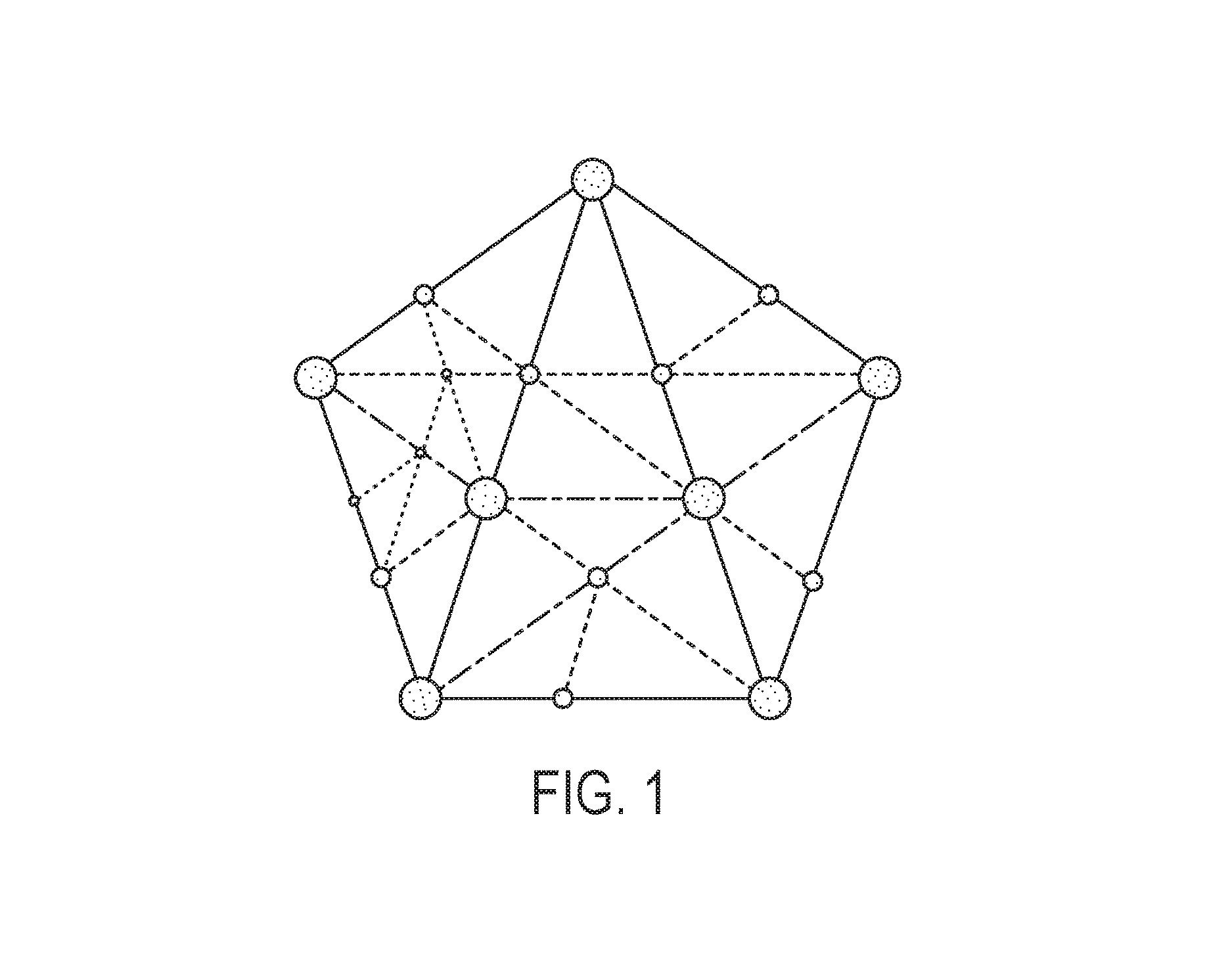
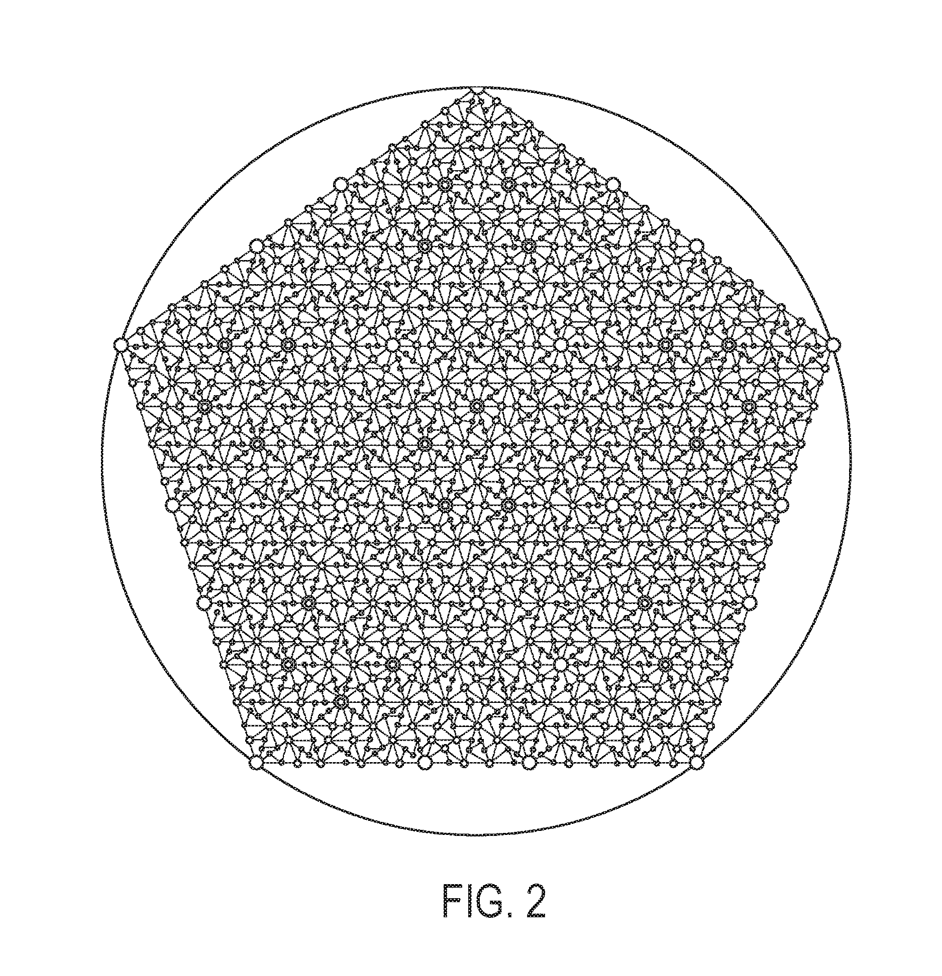
[0009]Described herein are systems and methods for adjusting one or more images of a sample to correct geometric distortions and / or to properly align the one or more images using a pattern of dots, e.g., arranged in a quasiperiodic lattice. By obtaining an image of the pattern of dots with a camera, it is possible to compare the imaged positions of the dots with the expected (actual) positions of the dots of the pattern, and thus determine a geometric transformation applicable to the image that would shift the relative positions of the dots to their actual real-world positions. The same transformation can then be applied to an image of a sample (e.g., biological sample) or other object that is obtained using the same camera in the same configuration as used to obtain the image of the pattern of dots, thereby correcting distortion in the image. Similarly, in some embodiments, the approach works to simultaneously (or substantially simultaneously) register multiple images of the same sample with respect to each other and / or correct those images for distortion.
[0010]In some embodiments, the use of a quasiperiodic lattice offers a number of benefits over the use of a periodic lattice to register multiple images with respect to each other and / or to correct the images for distortion. One of the benefits of using a quasiperiodic lattice over a periodic lattice is that a number of possible errors of registration by a grid period may be avoided, while at the same time the average grid density may be preserved, allowing for the use of the quasiperiodic lattice to correct image aberrations over the entire field of interest. Furthermore, defined (e.g., quantized) geometric characteristics such as distances to nearest neighbors in principle directions (quantized angles) of the lattice are also preserved by using a quasiperiodic lattice. Dots of the lattice can therefore be identified and a dictionary characterizing each dot with an alphanumeric character string and logging its xy-position can be created. The dictionary can be used to search for expected xy-positions of dots identified in an image of the quasiperiodic pattern.
[0012]In some embodiments, the pattern of dots is a quasiperiodic pattern that has one, two, three, or all four of the following properties: (i) local uniqueness, that is, by scanning a large-enough portion of an image of the pattern, it is possible to identify the correct portion of the pattern; (ii) approximately uniform local density of dots; (iii) ability to match an imaged dot with its expected location in the pattern from easily-identified, quantized nearest neighbor relations; and (iv) pattern elements have a discrete set of possible mutual positions. Here, local uniqueness does not necessarily require that there be only a single dot in the entire pattern with the same nearest neighbor relations. Because multiple dots are identified in the image (e.g., from about 10 to about 600, e.g., from about 10 to about 50, from about 10 to about 100, from about 100 to about 300, from about 200 to about 500, from about 400 to about 600, etc.), there will be an area of dots that are close together (accumulation area), and the correct corresponding dots can be identified based on the location of the accumulation area. Thus, in some embodiments, a pattern can have millions of dots (e.g., 1 to 5 million, e.g., 2 million dots), and it is still possible to very quickly scan an image of the pattern and very quickly identify the corresponding correct locations.

Problems solved by technology

Acquired images may contain geometric distortions—such as radial, projective, and spherical distortions, and chromatic aberration—that can be difficult to correct.
Such registration tasks may be complicated by the existence of geometric distortions in the individual images.
Furthermore, with more than a single field of view, the shift in the field of view in real space is not accurately known.
However, various difficulties may be encountered when using real beads as a test pattern for image adjustment.
One of the difficulties is that different magnifications require different bead sizes.
In addition, beads may not properly disperse, or they may be too difficult to image clearly.
Moreover, the imaging and image correction procedure can be tedious and time consuming.

Method used


Image

  • Method and system for image correction using a quasiperiodic grid
  • Method and system for image correction using a quasiperiodic grid
  • Method and system for image correction using a quasiperiodic grid

Examples


Embodiment Construction

[0049]It is contemplated that apparatus, systems, devices, methods, and processes of the claimed invention encompass variations and adaptations developed using information from the embodiments described herein. Adaptation and / or modification of the systems, devices, methods, and processes described herein may be performed by those of ordinary skill in the relevant art.

[0050]Throughout the description, where apparatus, articles, devices, and systems are described as having, including, or comprising specific components, or where processes and methods are described as having, including, or comprising specific steps, it is contemplated that, additionally, there are articles, devices, and systems of the present invention that consist essentially of, or consist of, the recited components, and that there are processes and methods according to the present invention that consist essentially of, or consist of, the recited processing steps.

[0051]It should be understood that the order of steps ...


PUM


Abstract

Described herein is a method for adjusting one or more images of a sample to correct geometric distortions and / or to properly align the one or more images using a pattern of dots, e.g., a quasiperiodic grid.

Description

CROSS-REFERENCE TO RELATED APPLICATIONS[0001]This application claims priority to, and the benefit of, and incorporates herein by reference in its entirety, U.S. Provisional Patent Application No. 61 / 926,246, filed Jan. 10, 2014.TECHNICAL FIELD[0002]This invention relates generally to methods and systems for image correction. More particularly, in certain embodiments, the invention relates to image correction using a quasiperiodic grid.BACKGROUND[0003]Acquired images may contain geometric distortions—such as radial, projective, and spherical distortions, and chromatic aberration—that can be difficult to correct. For example, it is desirable to correct a set of microscopy images acquired with one or more cameras (e.g., each capturing different spectral bands) for geometric distortions, or other optical aberrations or artifacts. Image correction is particularly important in applications such as the imaging of biological samples for clinical or research purposes, where acquired images m...

Claims


Application Information

Patent Timeline
Patent Type & Authority Patents(United States)
IPC IPC(8): G06K9/46G06T5/00G06T7/00G06K9/50
CPCG06T5/006G06K9/4604G06T7/80G06T7/30G06T2207/10004G06T7/337
Inventor PALO, KAUPO
Owner PERKINELMER CELLULAR TECH GERMANY GMBH
Why Eureka
Try Eureka