Method for manufacturing a capacitive storage element, storage element and its use

a technology of capacitive storage elements and manufacturing methods, applied in the direction of capacitors, fixed capacitor details, fixed capacitors, etc., can solve the problems of difficult to achieve thickness which ensures adequate dielectric strength, the design of titanate layers as layers, and the current cost of lithium ion batteries approximately 1,000 euro per kwh

Active Publication Date: 2017-02-28
ROBERT BOSCH GMBH
View PDF13 Cites 0 Cited by
  • Summary
  • Abstract
  • Description
  • Claims
  • Application Information

AI Technical Summary

Benefits of technology

[0007]In an example method according to the present invention, an external electrical field is applied in the direction of the layer sequence to form a closed titanate layer having an adjustable minimal layer thickness, and when the field is applied, a fluid containing titanate particles is applied to the substrate. The method according to the present invention may have the advantage that the titanate particles are concentrated in the protruding places (or in the protruding areas) of the porous substrate, since a higher field line density of the electrical field results there due to the shape of the substrate and its dielectric properties. Furthermore, the layered nature of the titanate layer may be ensured with relatively little effort through this method, i.e., it is possible to achieve a ratio, which is not excessively high, of the layer thicknesses in places having the greatest layer thickness and in places having the smallest layer thickness.
[0008]While applying the titanate particles dissolved in the fluid, the electrical field is applied transversely, in particular perpendicularly, to the plane of the layer(s). This should result in the titanate being concentrated to the greatest possible extent in the places of the greatest electrical field line density. This ensures a layered structure, which does not leave behind any critically thin places at the tips or elevated places of the substrate. As a result, the layer thickness of the titanate layer is applied with a sufficient uniformity with respect to the electrical field distribution. This in turn allows for the smoothest possible sliding of the substrate protrusions to achieve the high number of planes.
[0010]According to another preferred specific embodiment of the present invention, it is provided that the forming closed titanate layer is then heated to 700° C. to 900° C. with continued application of the field. This heating creates a stable and long-lasting titanate layer.
[0020]If it is assumed that a 100 km driving range of a motor vehicle having an electric drive requires 15 kWh, then assuming a lithium ion battery as the electrical energy storage unit, one would need a battery weight of 75 kg / 100 km. Thus, with a suitable vehicle having a range of 500 km, a battery weight of 350 kg would be needed. Furthermore, a lithium ion battery currently costs approximately 1,000 Euro per kWh. Such a rechargeable battery for a range of 500 km would thus cost approximately 75,000 Euro. An energy storage unit having the aforementioned capacitive storage element should be considerably less expensive per kWh.

Problems solved by technology

However, since the substrate, designed as a mold, of such a capacitive storage element is porous, the design of the titanate layer as a layer which is designed as a through-layer having a thickness which ensures adequate dielectric strength is not easy to achieve since the titanate is deposited preferably in the recesses in the porous substrate, while the protruding parts of the porous substrate remain uncovered by titanate or are only inadequately covered.
In addition, costs and environmental safety also play a crucial role in the selection of the type of energy storage unit.
Furthermore, a lithium ion battery currently costs approximately 1,000 Euro per kWh.

Method used


Image

  • Method for manufacturing a capacitive storage element, storage element and its use
  • Method for manufacturing a capacitive storage element, storage element and its use
  • Method for manufacturing a capacitive storage element, storage element and its use

Examples


Embodiment Construction

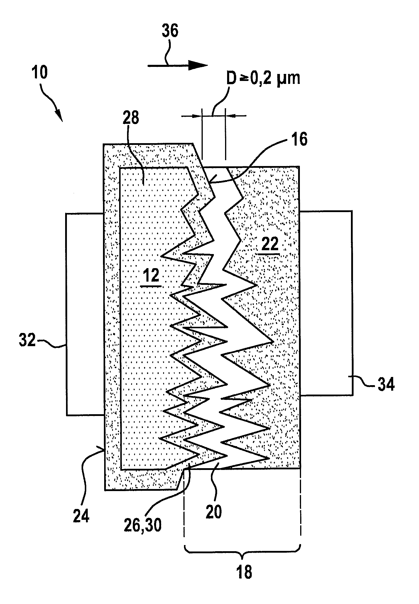
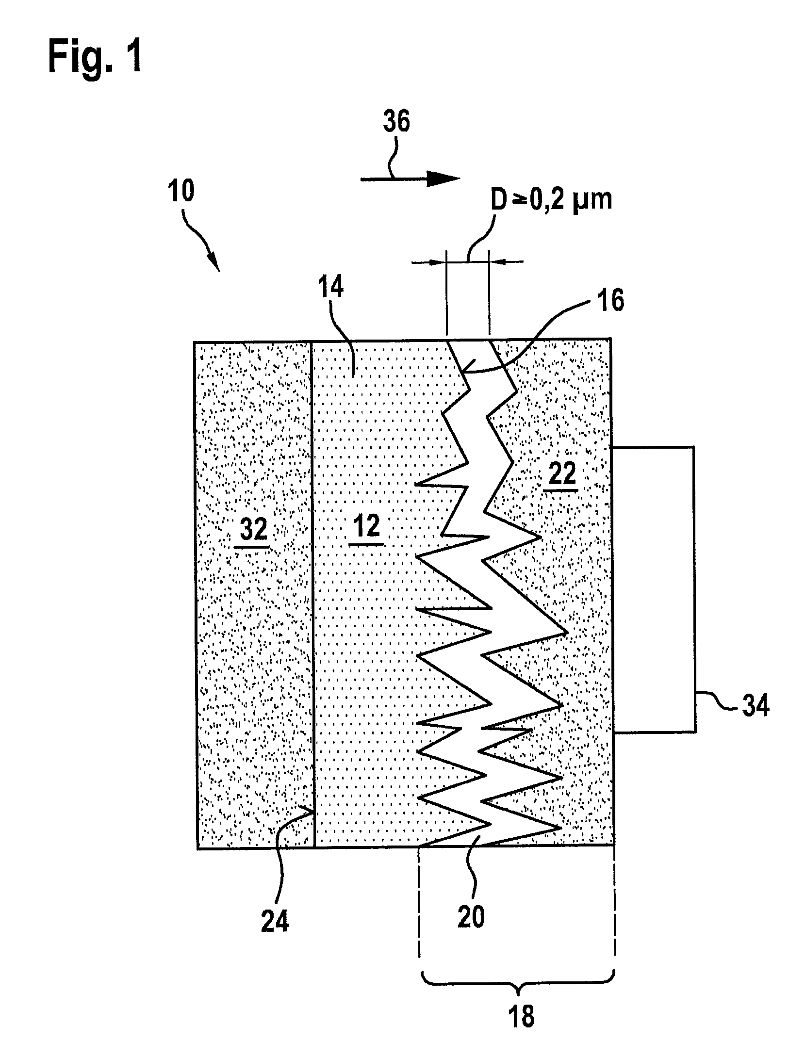
[0025]FIG. 1 shows a capacitive storage element 10 having a porous substrate 12 and a layer system 18 on one side 16 of porous substrate 12. Porous substrate 12 of FIG. 1 is designed as a conductive substrate 14. Such a conductive porous substrate 14 is an activated carbon body, for example. Layer system 18 on one side 16 of substrate 12 is a layer system 18 having a layer sequence of a closed dielectric titanate layer 20 and an electrically conductive layer 22. The porous nature of substrate 12 is shown in the schematic view of FIGS. 1 and 2 only on the one side 16 facing dielectric titanate layer 20 and electrically conductive layer 22 but is also present in principle on the other side 24 of substrate 12 opposite the one side 16.

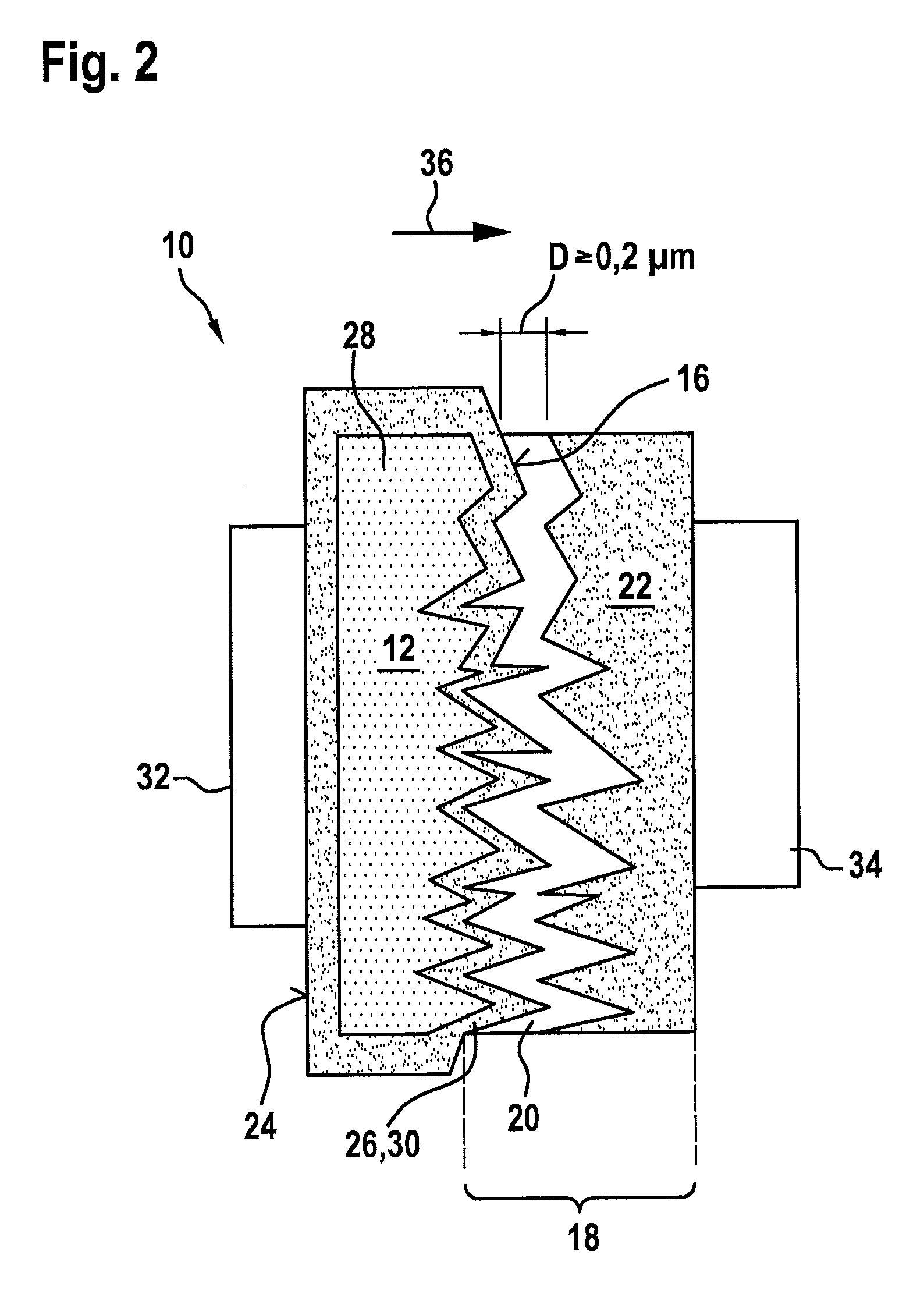
[0026]FIG. 2 also shows a capacitive storage element 10 having a porous substrate 12 and a layer system 18 on one side 16 of porous substrate 12. However, porous substrate 12 of FIG. 2 is completely covered by a conductive surface layer 26 and is thus a su...


PUM

PropertyMeasurementUnit
thicknessaaaaaaaaaa
thicknessaaaaaaaaaa
weightaaaaaaaaaa

Abstract

A method for manufacturing a capacitive storage element having a layer system on one side of a porous substrate, which is designed as a conductive substrate or has a conductive surface layer at least on the one side, the layer system having a layer sequence of a dielectric titanate layer and an electrically conductive layer. It is provided that to form a closed titanate layer having an adjustable minimum layer thickness, an external electrical field is applied in the direction of the layer sequence, and when the field is applied, a fluid containing titanate particles is applied to the substrate. A corresponding capacitive storage element and the use of a capacitive storage element as a storage element of an electrical energy storage unit for supplying energy to an electric drive or hybrid drive of a motor vehicle are also described.

Description

FIELD[0001]The present invention relates to a method for manufacturing a capacitive storage element having a layer system on one side of a porous substrate, which is designed as a conductive substrate or has a conductive surface layer at least on the one side, the layer system having a layer sequence of a dielectric titanate layer and an electrically conductive layer. The present invention also relates to a capacitive storage element for an electrical energy storage unit for supplying energy to an electric drive or a hybrid drive of a motor vehicle as well as its use as a storage element of an electrical energy storage unit for supplying energy to an electric drive or a hybrid drive of a motor vehicle.BACKGROUND INFORMATION[0002]German Patent Application No. DE 102 21 498 A1 describes a method for manufacturing a capacitor having an inert porous mold to which a first electrically conductive layer, a barium titanate layer, and then an electrically conductive layer are applied.[0003]H...

Claims


Application Information

Patent Timeline
Patent Type & Authority Patents(United States)
IPC IPC(8): H01G4/12H01G11/52B60L11/18B60L11/00
CPCH01G4/12B60L11/005B60L11/1879H01G4/1218H01G11/52Y02T10/7005Y02T10/705Y02T10/7022Y10T29/435B60L50/40B60L50/64Y02T10/70
Inventor WALCH, BERT
Owner ROBERT BOSCH GMBH
Why Eureka
Try Eureka