Charged powder supply device

a technology of powder supply device and charge device, which is applied in the direction of electrographic process, instruments, coatings, etc., can solve the problems of difficult control of difficult to control the coating amount of phosphor in different areas of the object, and difficult to control the diffusion direction of phosphor. achieve the effect of effective control of the action for

Inactive Publication Date: 2017-03-07
ACHROLUX
View PDF7 Cites 0 Cited by
  • Summary
  • Abstract
  • Description
  • Claims
  • Application Information

AI Technical Summary

Benefits of technology

[0019]Therefore, the present invention forms a powder layer on objects through the charged powder supply device. That is, the action force acts on the carrier to vibrate the charged powder particles, thereby causing the charged powder particles to leave the carrier so as to be attached to the objects under the effect of an electric field. By vibrating the charged powder particles through the carrier, the present invention can effectively control the action force on each vibrating position of the carrier such that the vibrated charged powder particles on each vibrating position of the carrier have a uniform height. Accordingly, the charged powder particles are uniformly attached to the objects.

Problems solved by technology

During coating, it is difficult to control the coating amount of phosphor in different areas of the object and consequently the phosphor in different areas often has different thicknesses.
However, it is difficult to control the diffusion direction of the phosphor.
However, since it is difficult to control the direction of the air flow A after it passes through the micro-holes of the fluidized board 10, undirected flows, such as turbulent flows, can easily occur, especially after the air flow A arrives at and then bounces back from the receiving member 12.

Method used


Image

  • Charged powder supply device
  • Charged powder supply device
  • Charged powder supply device

Examples


first embodiment

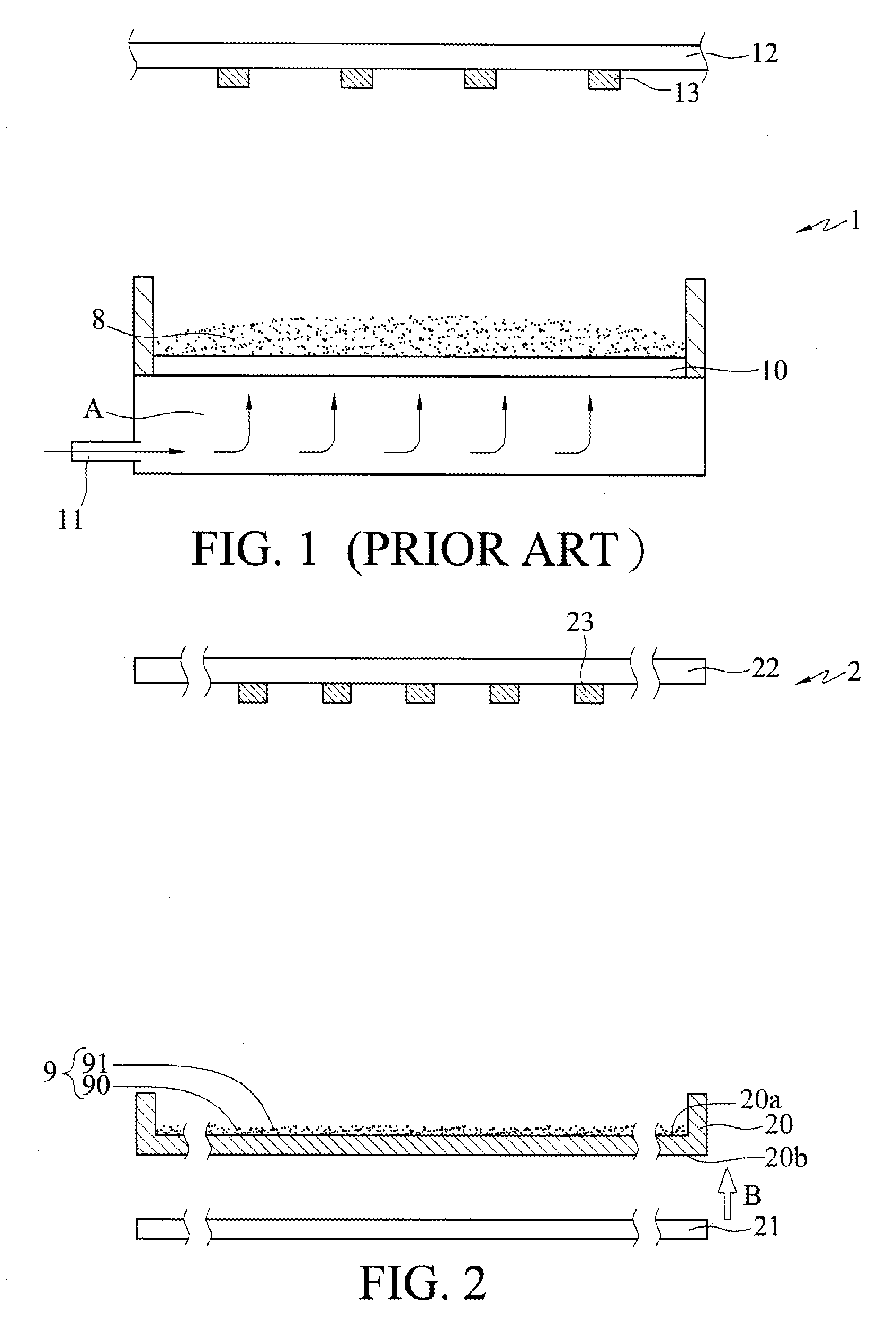
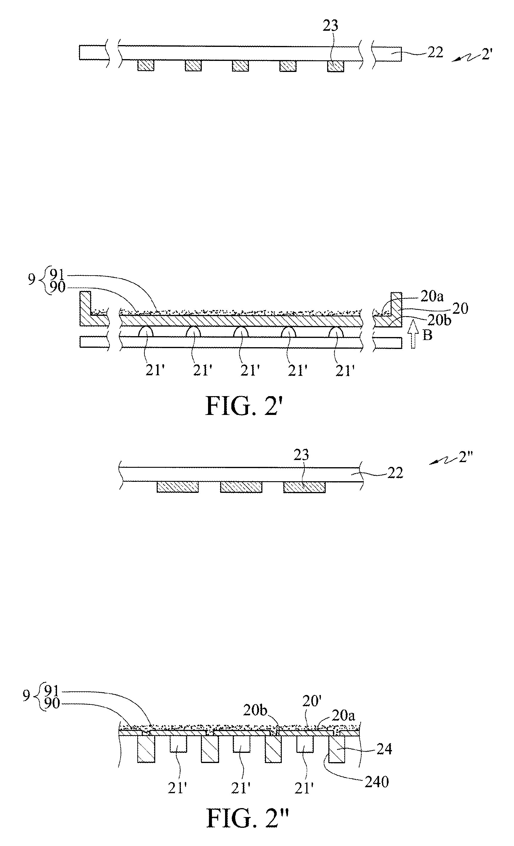
[0030]FIGS. 2, 2′ and 2″ are schematic cross-sectional views showing charged powder supply devices 2, 2′, 2″ according to the present invention.

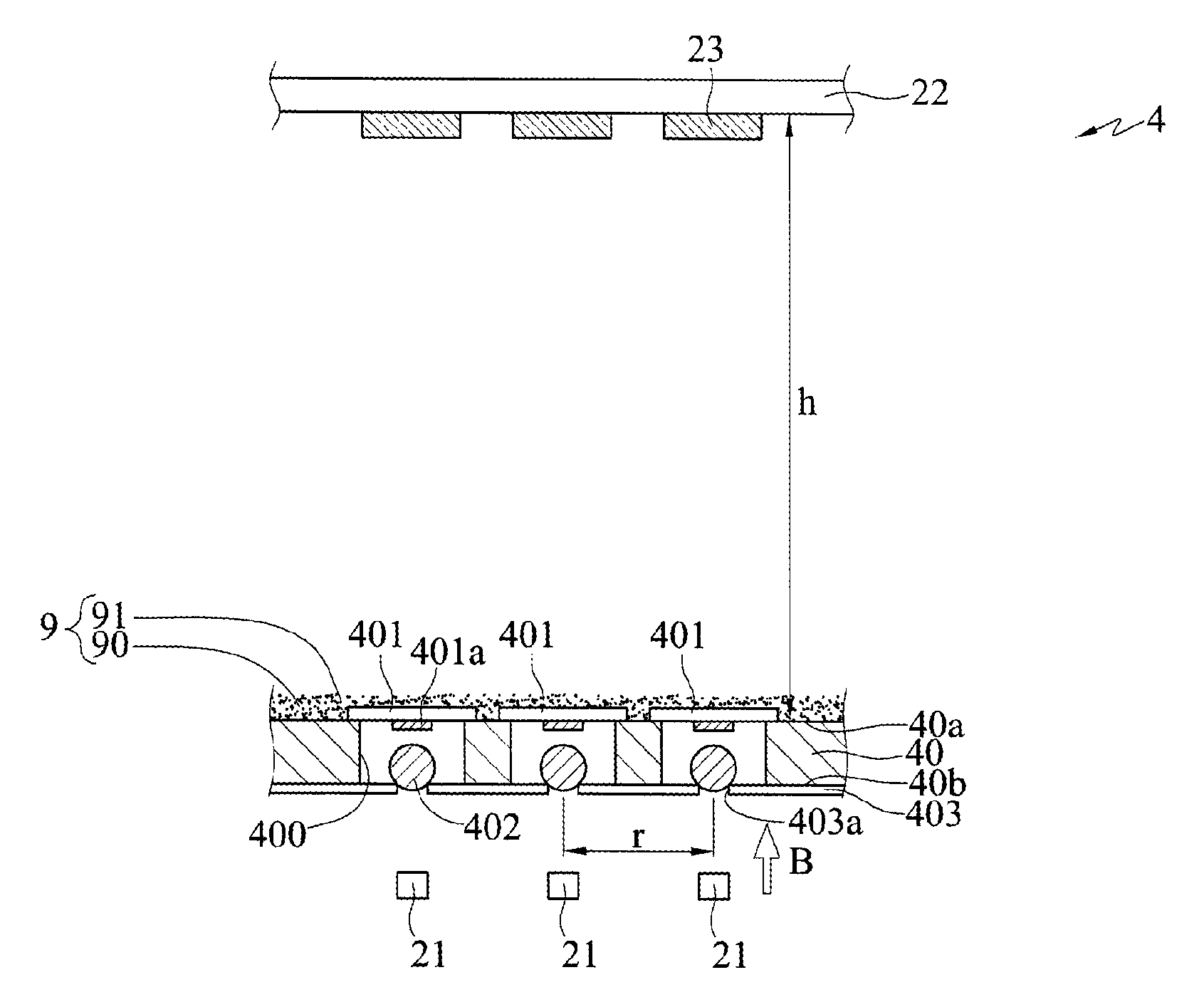
[0031]Referring to FIG. 2, the charged powder supply device 2 has a carrier 20, an action source 21 and a receiving member22.

[0032]The carrier 20 has a first side 20a with powder 9 disposed thereon and a second side 20b opposite to the first side 20a. The powder 9 has a plurality of powder particles 90 and an adhesive material 91. For example, the adhesive material 91 is in the form of solid particles. The adhesive material 91 is adhered to or separated from the powder particles 90 or encapsulates the powder particles 90. The powder particles 90 can be phosphor, nano tube, quantum dot, carbon tube or graphene particles.

[0033]The action source 21 is positioned at the second side 20b of the carrier 20 and separated from the second side 20b and used for acting on the carrier 20 so as to vibrate the powder particles 90 and the adhesive material ...

fourth embodiment

[0063]FIGS. 6A and 6B are schematic cross-sectional views of charged powder supply devices 6, 6′ according to the present invention.

[0064]Referring to FIG. 6A, a plurality of power supplies 65 are disposed at the first side 20a of the carrier 20 for providing charges to the carrier 20, thereby generating a uniform electric field between the carrier 20 and the receiving member 22. Further, as described above, the powder particles 90 and the adhesive material 91 are negatively charged by a corona discharge (denoted by a minus sign in the drawing). The adhesive material 91 is in the form of solid particles. The adhesive material 91 can be attached to or separated from the powder particles 90 or encapsulate the powder particles 90. In other embodiments, the powder particles 90 and the adhesive material 91 can be positively charged.

[0065]In the present embodiment, the power supplies 65 are disposed over the powder particles 90 and the adhesive material 91. Alternatively, the powder parti...


PUM

PropertyMeasurementUnit
impact forceaaaaaaaaaa
distanceaaaaaaaaaa
speedaaaaaaaaaa

Abstract

A charged powder supply device is disclosed. A plurality of charged powder particles are disposed on an upper side of a carrier and at least an action source is positioned at a lower side of the carrier for acting on the carrier so as to vibrate the charged powder particles on the upper side of the carrier. As such, the vibrated charged powder particles are attached to objects to be coated, such as LEDs, under the effect of an electric field so as to form a powder layer, such as a phosphor layer. Since there are no other external forces that affect the moving direction of the charged powder particles, the powder layer can be uniformly formed on the objects.

Description

BACKGROUND OF THE INVENTION[0001]1. Field of the Invention[0002]The present invention relates to devices used for forming uniform powder layers on objects, and more particularly, to a charged powder supply device.[0003]2. Description of Related Art[0004]Along with the rapid development of electronic industries, electronic products are becoming lighter, thinner, shorter and smaller and developed towards high performance, high function and high speed.[0005]In a conventional LED fabrication process, phosphor is formed on an object by dispensing or coating. During coating, it is difficult to control the coating amount of phosphor in different areas of the object and consequently the phosphor in different areas often has different thicknesses. Also, the phosphor may be distributed on LEDs by a diffusion process. However, it is difficult to control the diffusion direction of the phosphor. As a result, the LEDs have different amount of phosphor formed thereon.[0006]FIG. 1 shows a conventio...

Claims


Application Information

Patent Timeline
Patent Type & Authority Patents(United States)
IPC IPC(8): B05B5/16B05C19/04H01L33/44B05C19/02B05C19/00B05B5/057
CPCB05B5/1683B05B5/057B05B5/1608B05C19/00B05C19/025B05C19/04H01L33/44B05C19/002H01L2933/0041H01L33/00H01L33/0004H01L33/50G03G15/0887
Inventor LING, PEICHINGLIU, DEZHONG
Owner ACHROLUX
Why Eureka
Try Eureka