Pick-and-place head and method for picking work-pieces

a technology for workpieces and pickers, applied in the field of picks, can solve the problems of unsuitable higher mass, increased cost, and component pick-up, and achieve the effect of efficient and reliable handling and efficient and reliabl

Active Publication Date: 2017-03-07
KLA CORP
View PDF33 Cites 4 Cited by
  • Summary
  • Abstract
  • Description
  • Claims
  • Application Information

AI Technical Summary

Benefits of technology

[0014]A general object of the present invention is to provide a pick-and-place head of simpler configuration, which can easily be reconfigured in order to change the number of work-pieces that can be handled at once, and which nonetheless provides for efficient and reliable handling of all the work-pieces to be processed.
[0015]Another object of the present invention is to provide a method for handling plural work-pieces at once in an efficient and reliable manner.
[0025]The pick-and-place head is moveable relative to the plurality of work-pieces. In an example embodiment of the above described type where the nozzles are arranged in rows the arrangement of the nozzles furthermore is such that as the pick-and-place head moves relative to the plurality of work-pieces the nozzles with individual vacuum supply follow the nozzles with shared vacuum supply. In this way work-pieces which failed to be picked up by nozzles with shared vacuum supply can be picked up most easily by the nozzles with individual vacuum supply without requiring additional reverse movements of the pick-and-place head. Such an arrangement of nozzles can be realized whether there is shared vacuum supply for each of a number of rows of nozzles or a vacuum supply shared by more than one row of nozzles.

Problems solved by technology

From such pockets no components can be picked up and a vacuum nozzle that is placed above such a pocket will not attain vacuum.
For high throughput, however, high accelerations are needed, hence, higher mass is undesirable, and besides also increases costs.
While the above has described a typical situation for handling electronic components using vocabulary current in that field, the problem shown in the above example is more general.
Furthermore, providing separate vacuum supplies and vacuum sensors for each nozzle renders the configuration of the pick-and-place head quite complex.

Method used


Image

  • Pick-and-place head and method for picking work-pieces
  • Pick-and-place head and method for picking work-pieces
  • Pick-and-place head and method for picking work-pieces

Examples


Embodiment Construction

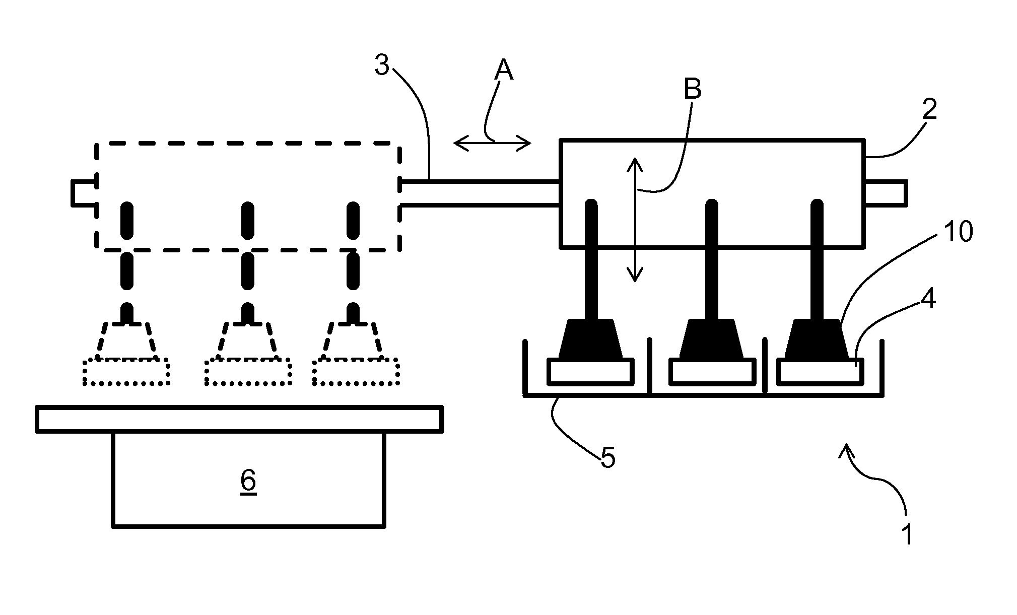
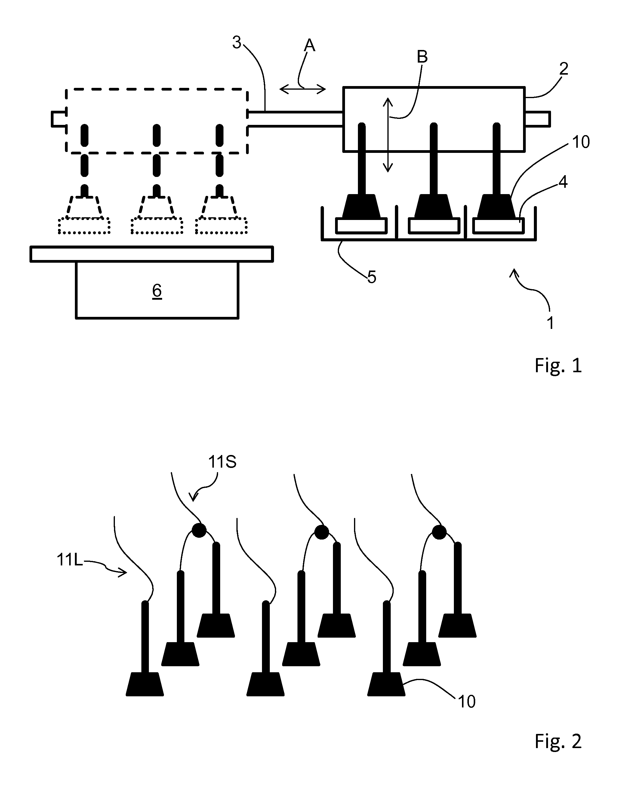
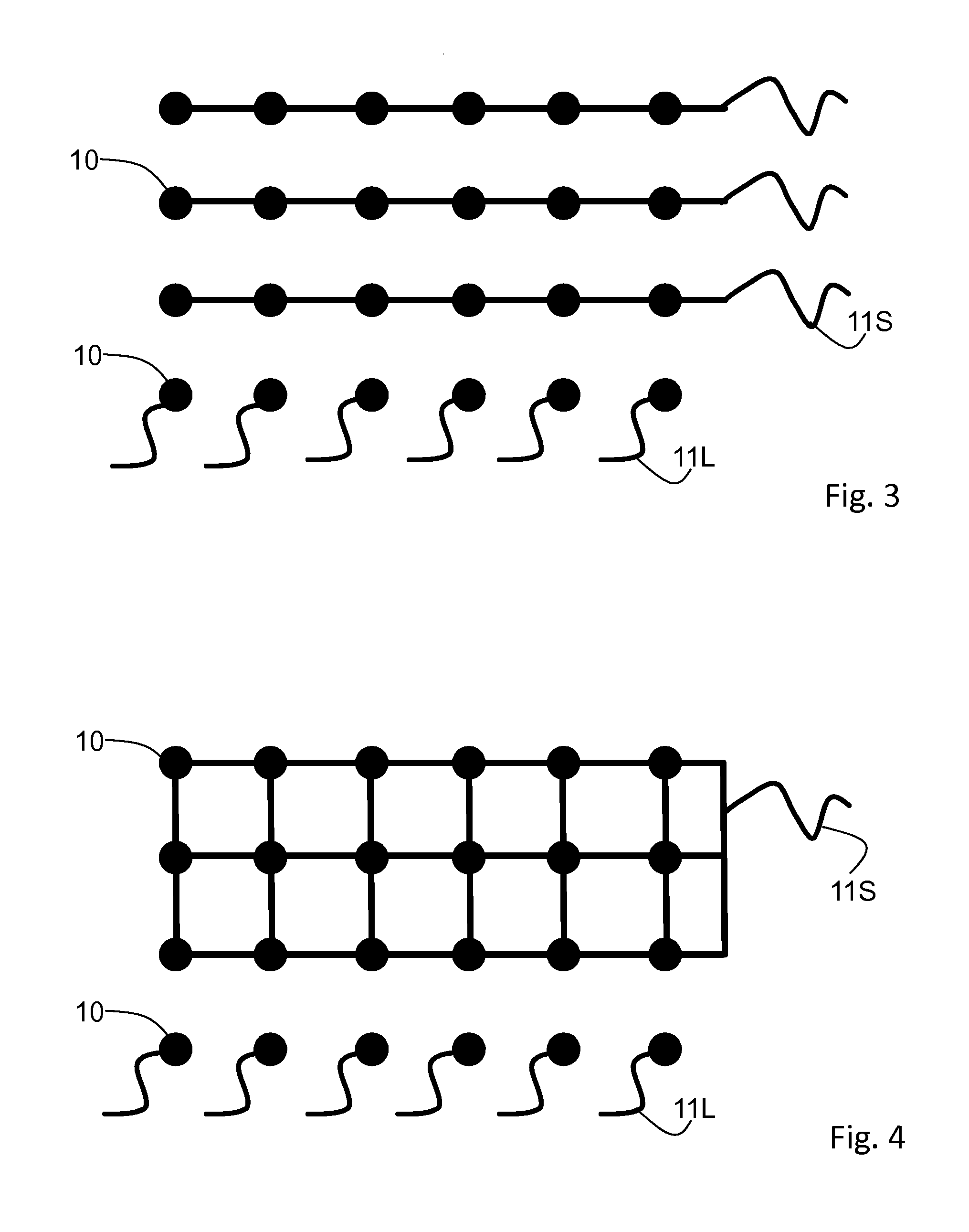
[0047]At the outset, it should be appreciated that like drawing numbers on different drawing views identify identical, or functionally similar, structural elements of the invention. While the present invention is described with respect to what is presently considered to be the preferred aspects, it is to be understood that the invention as claimed is not limited to the disclosed aspect. Also, it is to be understood that the invention is not limited in its application to the details of construction and the arrangement of the components set forth in the following description or illustrated in the drawings. The invention is applicable to other embodiments or of being practiced or carried out in various ways and is intended to include various modifications and equivalent arrangements within the spirit and scope of the appended claims.

[0048]Furthermore, it is understood that this invention is not limited to the particular methodology, materials and modifications described and as such may...


PUM


Abstract

A pick-and-place head for picking a plurality of work-pieces from at least one first location and for placing the plurality of work-pieces at least one second location is disclosed. The pick-and-place head exhibits a plurality of nozzles, wherein each nozzle is configured to engage one of the work-pieces by action of a vacuum. At least one nozzle has an individual vacuum supply and at least two further nozzles have a shared vacuum supply. A corresponding method is also disclosed, the method including the steps of approaching at least one of the plurality of work-pieces with a respective nozzle and then starting generation of a vacuum at each respective nozzle. The generation of vacuum in at least one nozzle is achieved by an individual vacuum supply, and generation of vacuum in at least two further nozzles is achieved by a shared vacuum supply of the at least two further nozzles.

Description

CROSS-REFERENCE TO RELATED APPLICATIONS[0001]This application is filed under 35 U.S.C. §111(a) and §365(c) as a continuation of International Patent Application No. PCT / US2014 / 064841, filed on Nov. 10, 2014, which application claims the benefit of U.S. Provisional Patent Application No. 61 / 909,184, filed on Nov. 26, 2013, which applications are incorporated herein by reference in their entireties.TECHNICAL FIELD[0002]The present invention relates to a pick-and-place head for picking work-pieces from one location and placing them at a different location, as well as to a corresponding method. More specifically the present invention relates to a pick-and-place head and corresponding method wherein the picking of work-pieces is by action of a vacuum.BACKGROUND OF THE INVENTION[0003]Manufacturing of a product or assembly of some apparatus generally involves the handling of work-pieces, for example components to be assembled. In particular, these work-pieces need to be transported between...

Claims


Application Information

Patent Timeline
Patent Type & Authority Patents(United States)
IPC IPC(8): B25J15/06B25J15/00B65G47/91
CPCB25J15/0616B25J15/0052B65G47/917B65G47/918B25J15/0683B65G47/912B65G2249/04
Inventor TRUYENS, CARL
Owner KLA CORP
Why Eureka
Try Eureka