
Method and apparatus for conversion of liquid fuels in a reactor, use of an apparatus for conversion of liquid fuels

a technology of liquid fuel and apparatus, which is applied in the direction of gasification process details, combustion process, inorganic chemistry, etc., can solve the problems of inability to prevent radiation and its effects, large probability of fouling or coking, and inability to atomize, etc., to achieve reliable and efficient process, reduce or even prevent the build-up of solid residues, and reduce the effect of solid residues

Inactive Publication Date: 2019-05-21
CLEAN FUELS
View PDF6 Cites 0 Cited by
  • Summary
  • Abstract
  • Description
  • Claims
  • Application Information

AI Technical Summary

Benefits of technology

The invention aims to prevent the buildup of solid residue at the nozzle by reducing heat transfer through radiation. The nozzle is placed in a separate space from the chamber, minimizing the solid angle and resulting in reduced radiant heat transfer. This results in a cooler nozzle and prevents coking and fouling. The device is more reliable and efficient.

Problems solved by technology

Particularly radiation and its effects cannot be prevented by means of insulation.
In prior art devices the nozzle atomizes the liquid inside the chamber, the nozzle being inside or very close to the chamber with the associated large probability of fouling or coking.
Positioning the nozzle in a space separate from the chamber, according to the invention, has the drawback that atomization is no longer practically possible, or at least considerably less technically feasible.
If the liquid fuel gets in contact with such hot material surfaces, coking or fouling would again occur, and result in undesired blockage of the fuel feed.
Since the fuel is a coking fuel, the evaporation will lead to the formation of solid deposits at the surface of the evaporator body.

Method used


Image

  • Method and apparatus for conversion of liquid fuels in a reactor, use of an apparatus for conversion of liquid fuels
  • Method and apparatus for conversion of liquid fuels in a reactor, use of an apparatus for conversion of liquid fuels
  • Method and apparatus for conversion of liquid fuels in a reactor, use of an apparatus for conversion of liquid fuels

Examples


Embodiment Construction

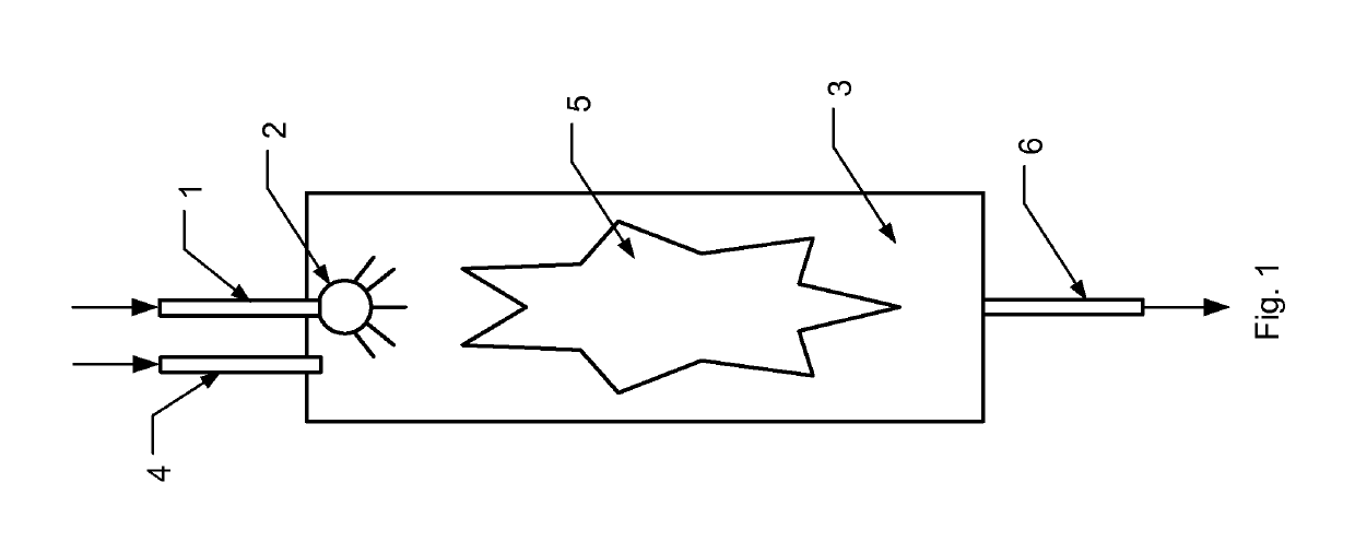
[0036]FIG. 1 illustrates a method and device as per the prior art. Via a liquid fuel line 1 which ends in a spray nozzle 2, fouling or coking liquid fuel is atomized inside chamber 3. Line 4 feeds a gaseous reactant into chamber 3. Inside chamber 3 a reaction takes place, for instance a flame 5 is created. Exhaust products leave chamber 3 via an exhaust 6.

[0037]In prior art devices a solid deposited matter frequently occurs at the nozzle tip. This results in clogging of the nozzle 2 and hence disruption of the supply of the fouling or coking liquid fuel in chamber 3, reducing the efficiency of the process and, after time, the need for removing the solid residue which often means down time for the reactor and thus a further reduced efficiency.

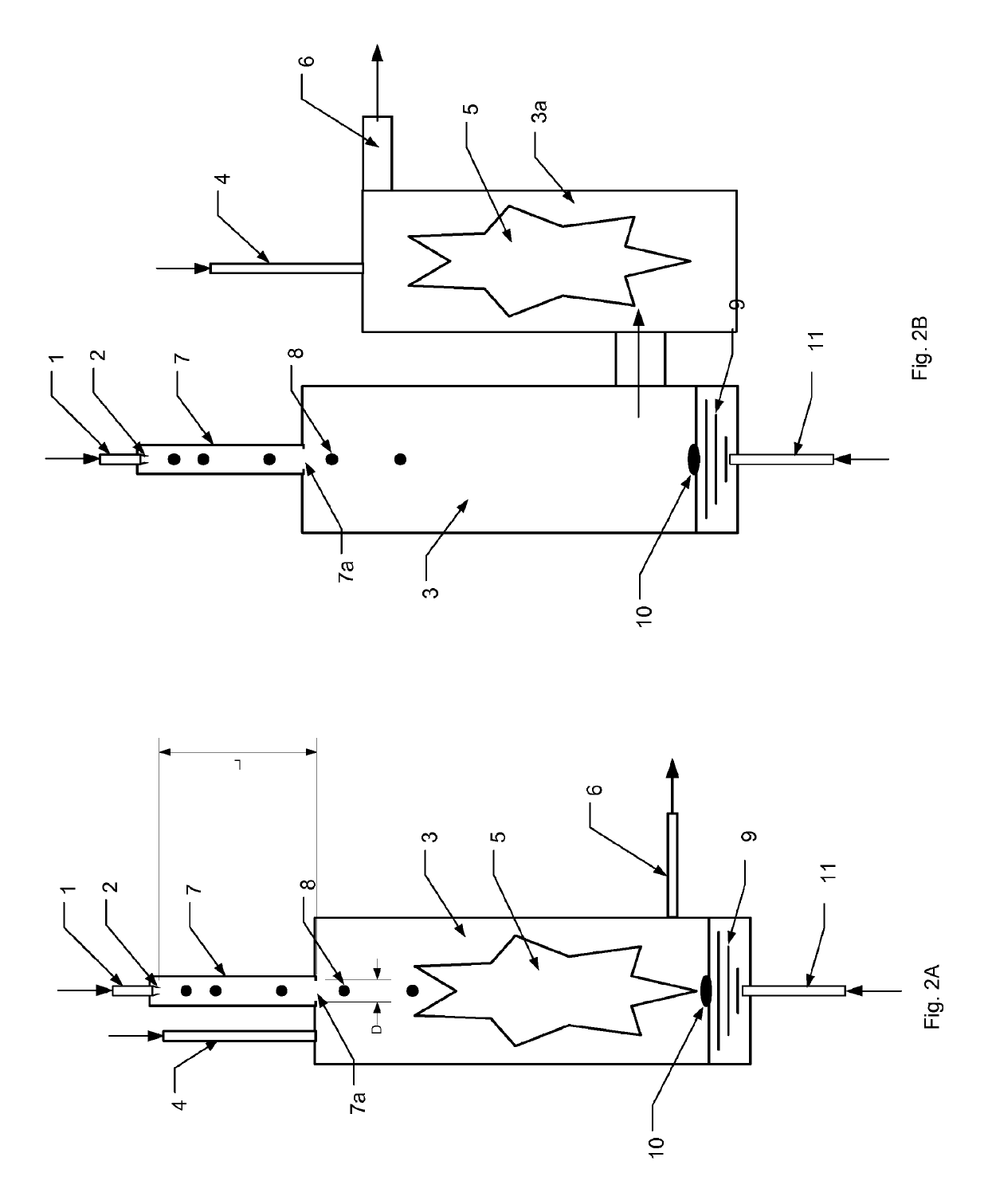
[0038]FIG. 2A illustrates a method and device according to the invention. The nozzle 2 is positioned remote from the reaction zone 5 at a spot with reduced radiation due to a small view factor of chamber 3. Preferably the nozzle is positioned in...


PUM

PropertyMeasurementUnit
solid angleaaaaaaaaaa
angleaaaaaaaaaa

Abstract

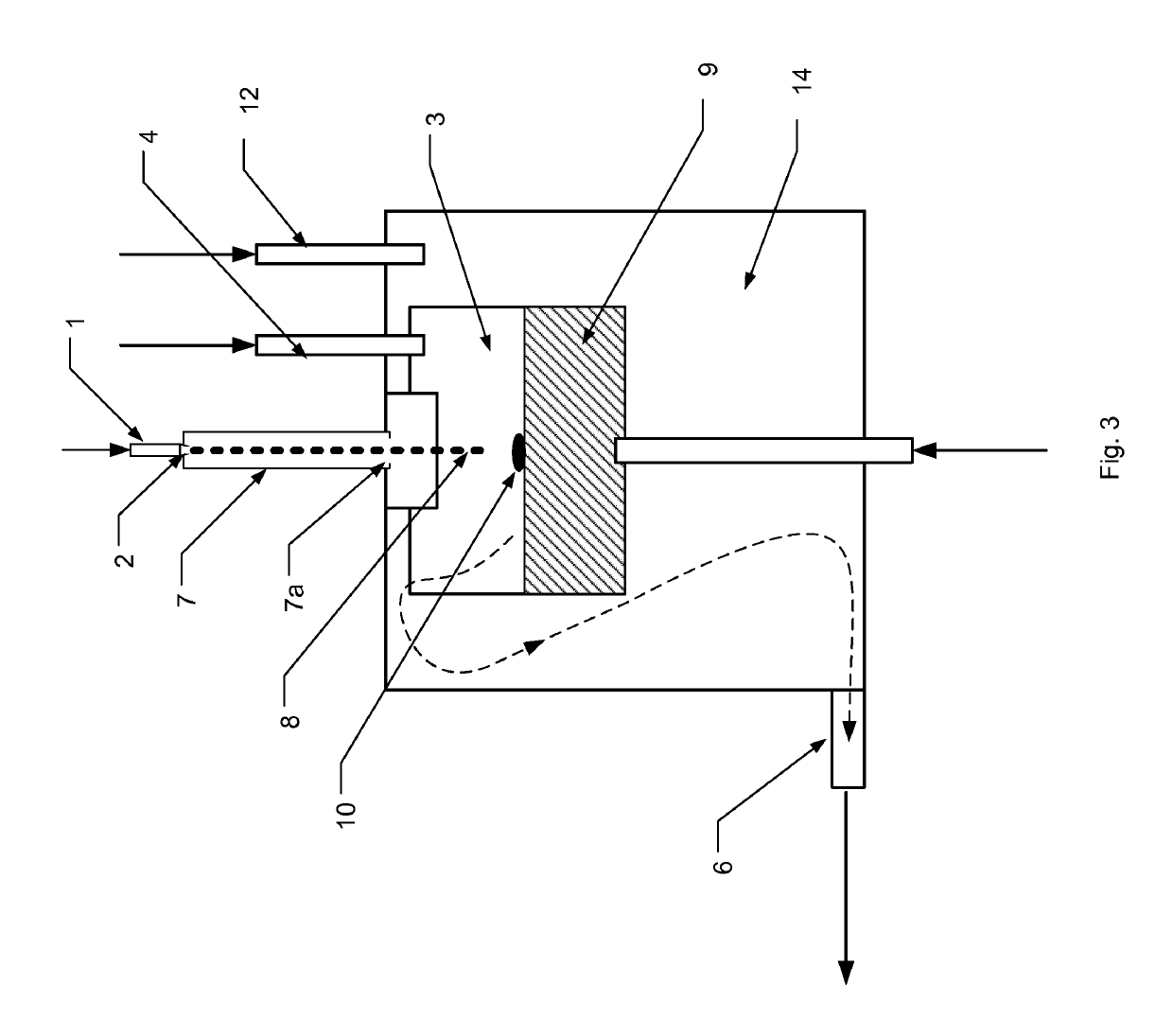
In an apparatus comprising a chamber (3) of a reactor drops (8) of a to be converted liquid are generated by a nozzle (2) positioned in a space (7) separate from the chamber (3). The drops (8) make a free fall thought the space 7 and enter via an opening (7a) the chamber (3) where they fall onto an evaporator body (9) for evaporation, the evaporated liquid leaves a solid deposit (1), A gaseous reactant line (11) supplies a reactant gas for conversion of the solid deposit (1) on the surface of the evaporator body.

Description

FIELD OF THE INVENTION[0001]The present invention relates to a method and an apparatus for the injection of coking liquid fuels into a reactor. The invention also relates to the use of an apparatus for the injection of coking liquid fuels.[0002]Coking liquid fuels are used in reactors for high-temperature chemical conversion, specifically in combustors and gasifiers, although they can also be used in or for gas turbines and even in reciprocating engines.BACKGROUND ART[0003]Known standard reactors comprise a nozzle for providing liquid fuel, an inlet for a gaseous reaction agent (such as air), a reaction chamber forming a reaction zone (such as a furnace or oven, or a gasifier or another high-temperature reactor) and an exhaust for exhausting the reaction product formed in the reaction zone. The thermal instability of liquid fuels is of concern for the operation and maintenance of many types of reactors (including reciprocating engines and gas turbines) and of gasification reactors. ...

Claims


Application Information

Patent Timeline
Patent Type & Authority Patents(United States)
IPC IPC(8): B01J19/26C10J3/48C01B3/22B01J19/00C01B3/02F23D7/00B01J4/00F23D9/00
CPCB01J4/002C01B3/02C01B3/22C10J3/48C10J3/485F23D7/00F23D9/00B01J19/0026F23D2900/00016B01J2219/00247C01B2203/0266C01B2203/0272C10J2200/152C10J2300/0916C10J2300/0956C10J2300/0976C10J2300/1637
Inventor SIEMONS, ROLAND
Owner CLEAN FUELS
Learn More