Moving color test pattern

a color test pattern and motion technology, applied in the field of video test patterns, can solve the problems of difficult for users to judge the precise point at which these colors converge to a uniform brightness, and optical blue filters (such as the wratten 47b filters), so as to facilitate the test of color processing fidelity and facilitate the calibration of color processing controls

Active Publication Date: 2017-03-07
PIXAR ANIMATION
View PDF5 Cites 3 Cited by
  • Summary
  • Abstract
  • Description
  • Claims
  • Application Information

AI Technical Summary

Benefits of technology

[0009]The present invention relates to video test patterns. More specifically, embodiments of the present invention provide improved test patterns and associated techniques for testing the fidelity of color processing (such as color dematrixing). One set of embodiments provide a test pattern that exhibits a large number of spatial interactions (e.g., edges) between colors corresponding to triples of constant value RGB primaries that incorporate a specific primary. In one embodiment, the test pattern includes at least one edge between each unique pair of colors. In a further embodiment, the specific primary is red. Another set of embodiments provide an animated sequence of test patterns that exhibit temporal interactions between the colors identified above. Yet another set of embodiments provide a test pattern comprising a plurality of zones, where distinct subsets of the zones are configured to exhibit independent visual changes in response to adjustments of specific color processing controls. Using these test patterns, users may more easily test the fidelity of color processing, and may more easily calibrate color processing controls accordingly.
[0013]According to another embodiment of the present invention, a method for testing the fidelity of color processing comprises receiving a first test signal representing a first test pattern, where the first test signal defines a first plurality of colors that appear in the first test pattern, and where the first plurality of colors exhibit a substantially similar brightness when viewed under a test condition in which only a single, predetermined primary is substantially visible; and receiving a second test signal representing a second test pattern, where the second test signal defines a second plurality of colors that appear in the second test pattern, where the second plurality of colors exhibit a substantially similar brightness when viewed under the test condition, and where the first test pattern and the second test pattern are visually distinct. In various embodiments, the method further comprises causing the first test pattern to be outputted, where the outputted first test pattern is generated from the first test signal, and where the outputted first test pattern exhibits a third plurality of colors distinct from the first plurality of colors; and causing the second test pattern to be outputted, where the outputted second test pattern is generated from the second test signal, and where the outputted second test pattern exhibits a fourth plurality of colors distinct from the second plurality of colors. An adjustment of one or more color processing controls is then received in response to viewing the outputted first and second test patterns, where the adjustment of the one or more color processing controls is intended to reduce an appearance of blinking when the outputted first and second test patterns are viewed in succession under the test condition.

Problems solved by technology

As a result, it may be difficult for users to judge the precise point at which these colors converge to a uniform brightness in the course of adjusting color and tint controls.
Another drawback is that optical blue filters (such as the Wratten 47B filter), which are commonly used in conjunction with the SMPTE color bars to block out red and green primaries, are relatively difficult and costly to manufacture.
Additionally, currently available blue filters cannot completely eliminate all visibility of red and green.
This reduces the accuracy of tint and color calibrations performed using the pattern.
Further, the effects of adjusting tint and color controls are interrelated, and the SMPTE color bars provide no guidance on how to adjust one control independently of the other.
If tint is set incorrectly, the pattern provides no visual feedback on how to properly adjust color.
Conversely, if color is set incorrectly, the pattern provides no visual feedback on how to properly adjust tint.
Thus, users must generally resort to trial and error in finding the exact combination of tint and colors settings that result in brightness convergence of the bars.

Method used


Image

  • Moving color test pattern
  • Moving color test pattern
  • Moving color test pattern

Examples


Embodiment Construction

[0031]In the following description, for the purposes of explanation, numerous specific details are set forth in order to provide an understanding of the present invention. It will be apparent, however, to one skilled in the art that the present invention may be practiced without some of these specific details. In other instances, well-known structures and devices are shown in block diagram form.

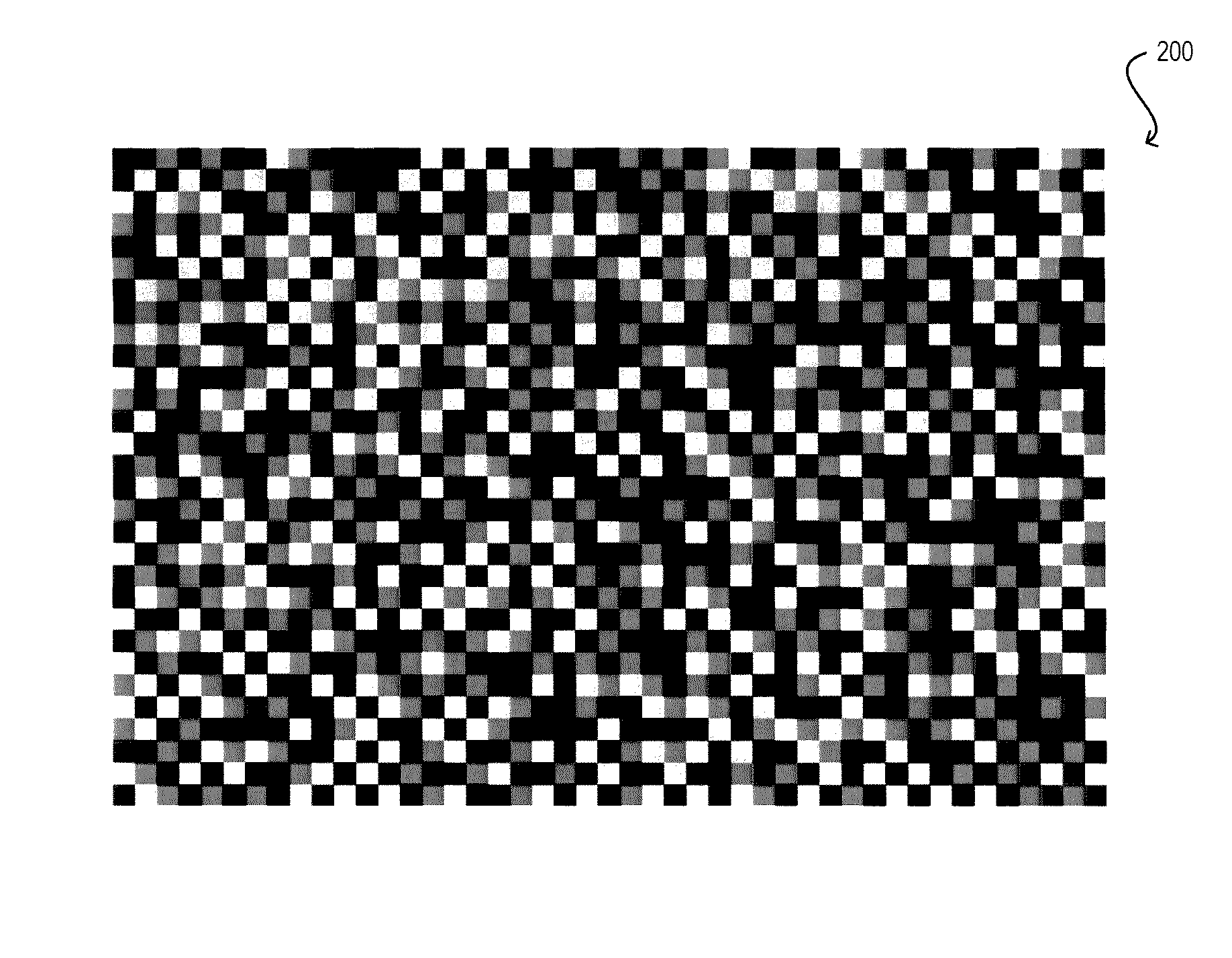
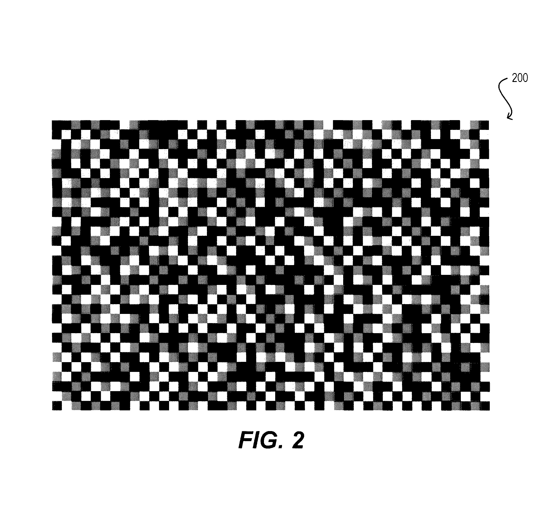
[0032]FIG. 2 illustrates a first test pattern 200 in accordance with an embodiment of the present invention. In one set of embodiments, test pattern 200 (or an encoded version thereof) may be stored on a machine-readable medium including but not limited to RAM, ROM, EEPROM, flash memory, CD-ROM, DVD-ROM, Blu-Ray Disc, HD-DVD or other optical storage, magnetic cassettes, magnetic tape, and magnetic disk storage or other magnetic storage. In other embodiments, test pattern 200 may be generated in real-time by a signal-generating device such as a dedicated test signal generator, DVD player, Blue...


PUM


Abstract

Test patterns and associated techniques for testing the fidelity of color processing are disclosed. One set of embodiments provide a test pattern that exhibits a large number of spatial interactions (e.g., edges) between colors corresponding to triples of constant value RGB primaries that incorporate a specific primary. Another set of embodiments provide an animated sequence of test patterns that exhibit temporal interactions between the colors identified above. Yet another set of embodiments provide a test pattern comprising a plurality of zones, where distinct subsets of the zones are configured to exhibit independent visual changes in response to adjustments of specific color processing controls. Using these test patterns, users may more easily test the fidelity of color processing (such as color dematrixing), and may more easily calibrate color processing controls accordingly.

Description

BACKGROUND OF THE INVENTION[0001]Embodiments of the present invention relate to video test patterns. More particularly, embodiments of the present invention relate to video test patterns and associated techniques for testing the fidelity of color processing.[0002]Traditional video systems (e.g., NTSC, ATSC, etc.) transmit and store color information as luminance and chrominance signals in a YCbCr (or Y′CbCr) color space. In contrast, traditional video pickup devices (e.g., video cameras, telecines, etc.), computers, and display devices (e.g., computer monitors, televisions, etc.) capture, generate, and display color information respectively as red, green, and blue primary signals in an RGB (or R′G′B′) color space. As a result, a color video signal is converted from RGB to YCbCr at the time of capture / generation, and then converted back to RGB from YCbCr at the time of display. These first and second conversions are known as “color matrixing” and “dematrixing.”[0003]Video output devi...

Claims


Application Information

Patent Timeline
Patent Type & Authority Patents(United States)
IPC IPC(8): H04N17/00H04N21/485
CPCH04N21/4854H04N5/76
Inventor SAYRE, RICKBOGART, ROD
Owner PIXAR ANIMATION
Why Eureka
Try Eureka