Shaving head with pivotable shaving unit

Active Publication Date: 2017-03-14
KONINKLJIJKE PHILIPS NV
View PDF39 Cites 14 Cited by
  • Summary
  • Abstract
  • Description
  • Claims
  • Application Information

AI Technical Summary

Benefits of technology

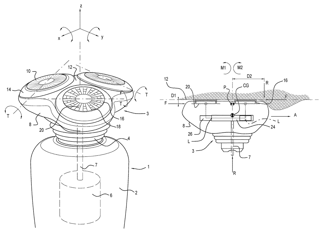
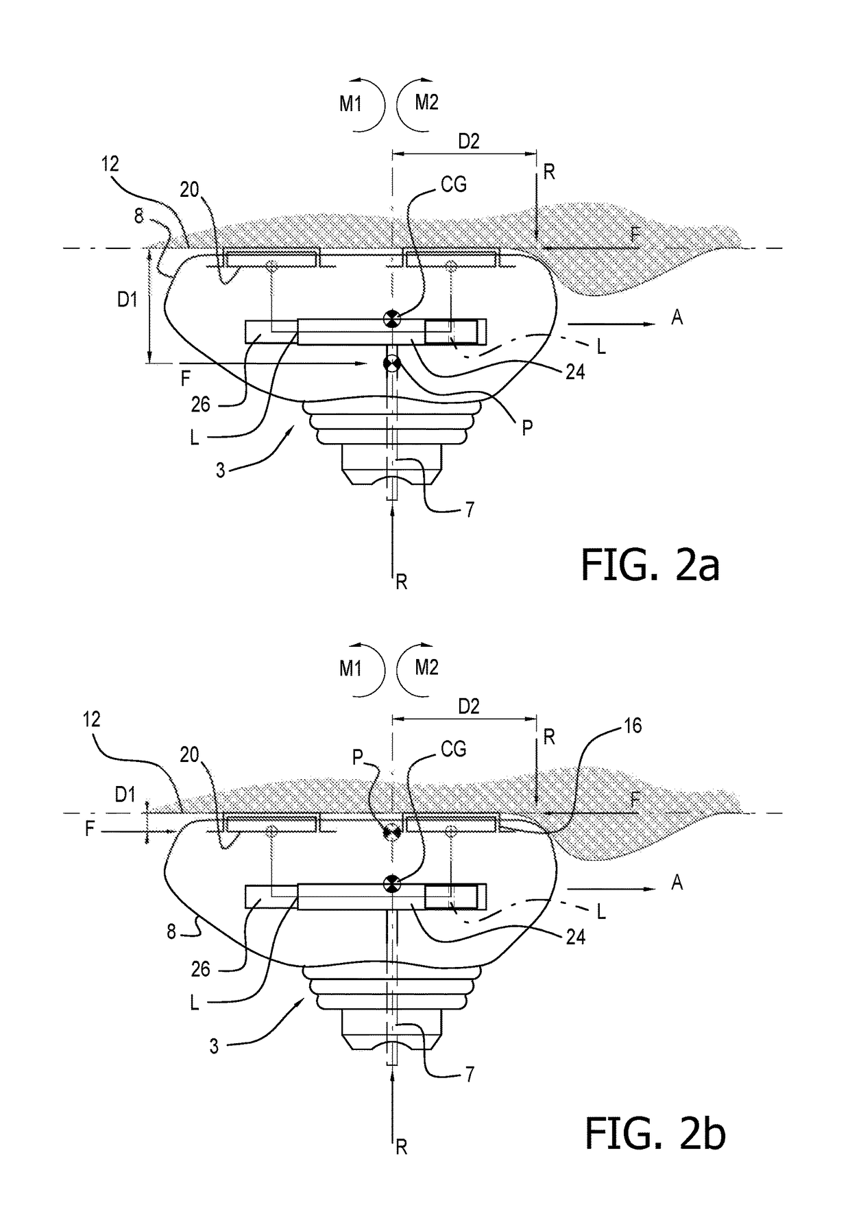
[0012]Preferably, the pivot structure defines a pivot point or pivot axis for the shaving unit relative to the support structure that is distanced from the skin contacting face by less than 12 mm, more preferably less than 10 mm, and most preferably less than 8 mm. As a general rule, it has been found that a relation exists between the distance from a pivot axis or pivot point to the leading edge of the skin contacting face of a shaver and the distance the pivot axis or pivot point is situated below the skin contacting face. For a stable geometry, a ratio of 3:1 should be maintained between these distances in order to prevent tipping of the pivotable shaving unit under the influence of friction forces between the skin and the cutting units when moving over the skin. By reducing the distance between the pivot axis and the skin contacting face, said ratio between said two distances is increased. In addition, other design choices are enabled, including for example a reduction of the pivoting stiffness of the shaving head of the shaving apparatus. At present, pivoting of a shaving head having two cutting units has usually been limited to the lengthwise direction, i.e. with the pivot axis being arranged transversally between the two external cutting members. As a result of the enhanced pivoting characteristics of the shaving head of the present invention, even shaving heads having two cutting units may be allowed to pivot about two axes.
[0015]In a still further embodiment of the invention, the position of the pivot point or pivot axis may be defined in terms of the distance between the centre of gravity of the pivotable shaving unit and the skin contacting face. Preferably, the pivot point or pivot axis is located at a distance from the skin contacting face that is less than or equal to the distance between said centre of gravity and the skin contacting face. Such a configuration allows the shaving unit to adopt a more stable position during shaving, and with such a configuration less biasing force is required to keep the shaving unit in a neutral position. It has in fact been determined that a biasing force that is four times less than that used in conventional geometries may be sufficient to keep the shaving unit in the neutral position.
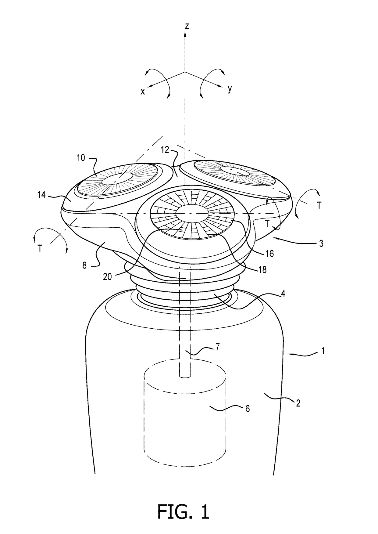
[0021]In a further embodiment, the shaving unit and the support structure comprise guides to prevent rotation of the shaving unit about an axis of the support structure extending perpendicularly to the skin contacting face. The guides may be integral with the pivot structure. This may be realized by using a Visman coupling element, which allows pivoting about two pivot axes while blocking rotation about a third axis extending perpendicularly to the two pivot axes. More preferably, the guides are located separate from the pivot structure e.g. in radially outward positions with respect to the centre of the shaving unit and a central axis of the support structure. It will be understood by the skilled person that, in order to reduce friction during the pivoting motion about the pivot axis, the bearing surfaces of the pivot structure should be in radial positions close to the pivot axis. For the purpose of preventing rotation of the shaving unit about the axis of the support structure, the guides should be at a radially larger distance from the pivot axis to reduce wear.
[0024]In a further embodiment, the pivot frame comprises a central portion carrying the stationary part of the pivot structure, wherein said central portion is connected to the support tube via lateral arms, and wherein the lateral openings are present between the lateral arms. The pivot frame and the support tube may mechanically interengage e.g. by the use of snap connectors allowing easy installation of the central driving member into the interior space of the support tube followed by easy assembly of the pivot frame and the support tube. The pivot frame may comprise a central portion forming the stationary part of the pivot structure for pivotal engagement with a movable part of the pivot structure mounted to the shaving unit. The pivot frame is connected to the support tube via the lateral arms. For a shaving unit with three cutting units, three such lateral arms may be provided, defining three lateral openings therebetween for enabling engagement of the central driving member with each of the driving members of the three cutting units. The lateral arms may form the guides discussed above for preventing rotation of the shaving unit about an axis of the support tube extending perpendicularly to the skin contacting face. To this end, the lateral arms may be accommodated within correspondingly shaped channels of the shaving unit. The support tube and the pivot frame may also be formed as an integral single element.

Problems solved by technology

Secondly, the cap carrier may be mounted to float or tilt with respect to the body of the shaver.

Method used


Image

  • Shaving head with pivotable shaving unit
  • Shaving head with pivotable shaving unit
  • Shaving head with pivotable shaving unit

Examples


first embodiment

[0040]FIG. 3 shows a shaving head 3 according to the invention, illustrating a partially sectioned perspective view of the shaving head 3 in which certain components have been removed for the sake of clarity. Shaving head 3 comprises a shaving unit frame 27 and a support tube 30. The support tube 30 is located in the neck 4 of the shaving apparatus 1 and connects to main housing 2 in a snap-fit arrangement at a coupling structure 29. A flexible bellows 31 covers the support tube 30. The flexible bellows 31 is resilient and tends to bias the shaving unit 8 to the neutral position as illustrated. At the upper end of the support tube 30, lateral openings 32 are formed between lateral support tube arms 34 of the support tube 30. Mounted on the lateral support tube arms 34 is a pivot frame 36 having lateral arms 38 that engage with the lateral support tube arms 34 in a snap connection 40. The support tube 30 and the pivot frame 36 together form a support structure 33 of the shaving head ...

third embodiment

[0051]According to an advantage of the third embodiment, the lower rim 256 is arranged at a distance from the support tube 230 such that the pivoting movement of the shaving unit frame 227 is limited to an angle α which in this case is defined by the angular distance from the neutral position to a point at which abutment between the lower rim 256 and support tube 230 occurs. These components may be manufactured robustly compared to the axle 248 and the lateral arms 238. In the event that the shaving apparatus is dropped, the impact of a blow on the shaving head 203 is likely to cause the shaving unit 208 to pivot about the support structure 233 to the maximum extent possible. This rotation is arrested by abutment of the lower rim 256 with the support tube 230, whereby damage to the lateral arms 238 may be prevented.

[0052]According to FIG. 6, it will be understood that when the shaving unit 208 is pivoted with respect to the support tube 230, the axle 248 carrying the central driving...


PUM


Abstract

A shaving head havinga shaving unit that includes a shaving unit frame with a skin contacting face, and at least two cutting units each having an external cutting member and an internal cutting member A pivot structure includes inter-engaging portions of a support structure and the shaving unit that enable the shaving unit to pivot relative to the support structure. Each internal cutting member is rotatable by a central driving member via a separate cutter driving member, the central driving member being configured to transmit a driving force to each cutter driving member in a transmission location. The pivot structure is located in an internal area of the shaving head between the skin contacting face, the cutter driving members and the transmission locations. The pivot structure further enables the central driving member and the cutter driving members to pivot together with the shaving unit relative to the support structure.

Description

[0001]This application is the U.S. National Phase application under 35 U.S.C. §371 of International Application No. PCT / EP2014 / 059302, filed on May 7, 2014, which claims the benefit of European Application No. 13167964.9 filed on May 16, 2013.BACKGROUND OF THE INVENTION[0002]1. Field of the Invention[0003]The present invention relates to a shaving head for a shaving apparatus of the rotary type and in particular to a shaving head having a pivotable shaving unit. The invention also relates to a shaving apparatus incorporating such a shaving head.[0004]2. Description of the Related Art[0005]Electric shavers are frequently used consumer items which generally comprise an assembly of moving and stationary cutting elements that interact to cut the hairs at the surface of a user's skin. In the case of rotary electric shavers, one or more cutting units, each comprising a rotary cutter and a cap, co-operate to cut the hairs. The cap contacts the skin and the cutter is driven by a motor locat...

Claims


Application Information

Patent Timeline
Patent Type & Authority Patents(United States)
IPC IPC(8): B26B19/14
CPCB26B19/146B26B19/145B26B19/14
Inventor OOSTERHOFF, HANSSTEUR, JELTE
Owner KONINKLJIJKE PHILIPS NV
Why Eureka
Try Eureka