Pneumatic tire

a technology of pneumatic tires and pneumatic wheels, which is applied in the field of pneumatic tires to achieve the effects of reducing the lowering of the snow discharge performance, improving the wandering resistance, and maintaining the on-snow traveling performan

Active Publication Date: 2017-03-14
TOYO TIRE & RUBBER CO LTD +1
View PDF16 Cites 0 Cited by
  • Summary
  • Abstract
  • Description
  • Claims
  • Application Information

AI Technical Summary

Benefits of technology

[0008]The present invention has been made in view of the above circumstances, and an object of the present invention is to provide a pneumatic tire which can improve wandering resistance without deteriorating on-snow traveling performance.Means for Solving the Problems
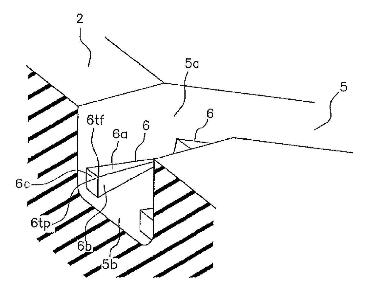
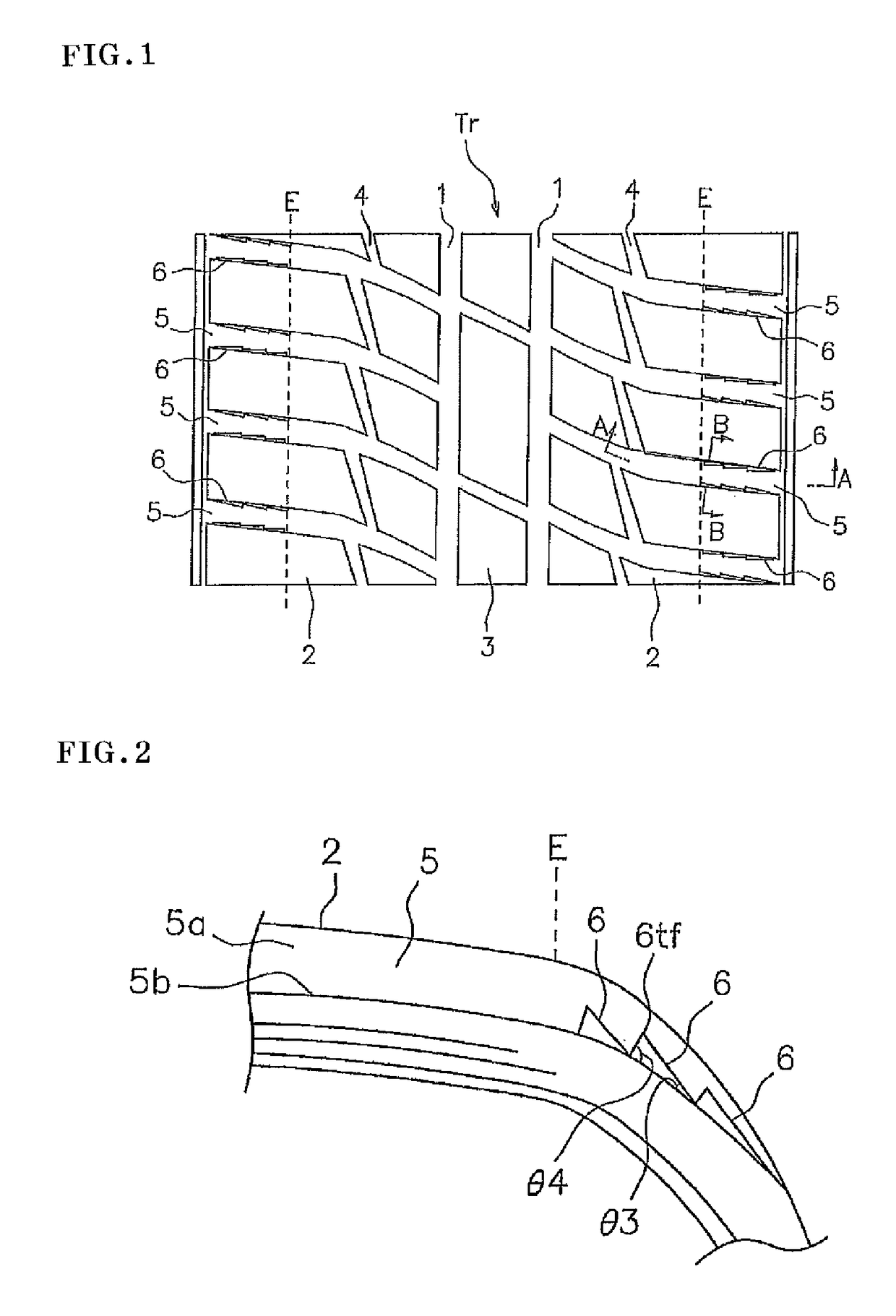
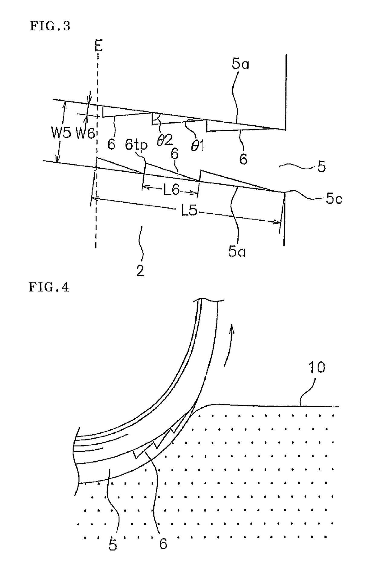
[0011]Further, since the shoulder lateral groove in the buttress area forms a discharge passage for snow and water, it is desirable to avoid installation of an obstacle preventing the snow discharge particularly in relation to the center portion in the groove width direction of the shoulder lateral groove. In this tire, since the projection protruding out of the wall surface of the shoulder lateral groove does not reach the center of the groove width of the shoulder lateral groove, a space is secured in the center portion in the groove width direction of the shoulder lateral groove, and it is possible to maintain the on-snow traveling performance while suppressing lowering of the snow discharge performance. As mentioned above, according to the pneumatic tire of the present invention, it is possible to improve the wandering resistance without deteriorating the on-snow traveling performance.
[0012]In the present invention, it is preferable that the projection protrudes out of a bottom surface in a corner portion of the shoulder lateral groove, and a height of the projection is smaller than a depth of the shoulder lateral groove. Since the projection protrudes out of the bottom surface of the corner portion, the rigidity of the projection can be effectively secured. As a result, it is possible to well generate an operation which pushes up the tire so as to make the tire escape from the rut, and an excellent wandering resistance can be achieved. Further, since the height of the projection is small, the lowering of the snow discharge performance can be suppressed, and the on-snow traveling performance can be valuably maintained.
[0013]In the present invention, it is preferable that a top portion of the projection is positioned in a center of a length of the projection or in an inner side in a tire width direction than the center, in a plan view and a front elevational view. According to the structure mentioned above, since the force for pushing up the tire can be easily obtained by the catch between the projection and the snow, it is possible to effectively improve the wandering resistance.
[0014]In the present invention, it is preferable that a length of the projection is equal to or less than 50% of a length of a wall surface of the shoulder lateral groove from the ground contact end to an outside end of the shoulder lateral groove. As a result, since a plurality of projections having an appropriate size can be easily lined up at the small distances in the buttress area, the wandering resistance can be valuably improved.

Problems solved by technology

On the contrary, it is thought that the tires described in the above documents do not generate an operation which is enough to make the tire escape from the rut due to a position where the projection is provided and a shape of the projection.

Method used


Image

  • Pneumatic tire
  • Pneumatic tire
  • Pneumatic tire

Examples


examples

[0049]In order to specifically show the structure and the effect of the present invention, the on-snow traveling performance and the wandering resistance were evaluated, and will be described. These evaluations were carried out in the following manners (1) and (2) by using a tire having a size 205 / 65R15.

[0050](1) On-Snow Traveling Performance

[0051]One passenger got on an actual car (FR sedan car of domestic 3000 cc class) to which test tires are installed, and evaluated according to a feeling test by executing straight traveling, turning and braking on a snowy road. The evaluation is made by setting a result of a comparative example 1 to 100, and the greater numerical value indicates the more excellent performance.

[0052](2) Wandering Resistance

[0053]One passenger got on the actual car to which the test tires are installed, and evaluated by feeling a wandering degree of the vehicle by traveling within a rut in a test course of a snowy road at a speed of 30 km / h. The evaluation is mad...


PUM


Abstract

A shoulder land portion is constructed by block rows. Shoulder lateral grooves sectionalize the block rows. The shoulder lateral grooves extend along the tire width direction in such a manner as to cut across ground contact ends. A plurality of projections is provided on a wall surface of the shoulder lateral groove. The projections protrude out of the wall surface of the shoulder lateral groove without reaching a center of a groove width of the shoulder lateral groove and are lined up in a length direction of the shoulder lateral groove in an outside area in the tire width direction from the ground contact end. The projection is formed into a triangular shape or a trapezoidal shape in its plan view and is formed into a triangular shape or a trapezoidal shape in its front elevational view.

Description

TECHNICAL FIELD[0001]The present invention relates to a pneumatic tire which can improve wandering resistance without deteriorating on-snow traveling performance.BACKGROUND ART[0002]In a studless tire which is used for traveling on a snowy road, there is generally employed a block pattern in which a lot of blocks are arranged on a tread surface. This is because traction (a tractional force) is enhanced by a snow column shear stress in a lateral groove which sectionalizes the blocks, thereby achieving improvement of the on-snow traveling performance. Further, during travel on a snowy road, a so-called wandering phenomenon tends to be generated, the wandering phenomenon being caused by vehicle meandering which is generated by the tire getting into a rut. Therefore, a method which can improve the wandering resistance is desired in this kind of tire.[0003]In Patent Documents 1 to 4, there is described a pneumatic tire in which a shoulder land portion positioned in an outermost side in a...

Claims


Application Information

Patent Timeline
Patent Type & Authority Patents(United States)
IPC IPC(8): B60C11/04B60C11/11B60C5/00B60C11/01B60C11/13B60C11/03
CPCB60C11/1307B60C5/00B60C11/01B60C11/0316B60C11/11B60C11/13B60C2011/0358B60C2011/1338B60C2011/1361
Inventor YASUNAGA, TOSHIKAZU
Owner TOYO TIRE & RUBBER CO LTD
Why Eureka
Try Eureka