
Wastewater evaporator

a wastewater evaporator and wastewater technology, applied in separation processes, filtration treatment, distillation by vibration, etc., can solve the problems of limiting the area where such tanks and drain field systems may be installed, limiting the available area for new homes, business and industrial construction, and increasing government regulations concerning such installations. , to achieve the effect of enhancing evaporation and increasing the surface area

Active Publication Date: 2017-03-14
CLARK GRETCHEN B +1
View PDF17 Cites 12 Cited by
  • Summary
  • Abstract
  • Description
  • Claims
  • Application Information

AI Technical Summary

Benefits of technology

The patent describes a system that uses air to help evaporate water in a tank. The air is introduced through a manifold and flows across the evaporator trays, where it cools the water. An air pump or fan may be used to push the air into the tank, and a vent may be provided to release the air. The trays may also have ultrasonic generators to improve the evaporation process by increasing the surface area of the water.

Problems solved by technology

However, they require soil that is capable of absorbing all of the liquid introduced into the system, which limits the areas where such tank and drain field systems may be installed.
Areas with high water tables and very rocky ground with poor absorption are clearly not suited for such systems, which limits the available areas for new home, business, and industrial construction.
Government regulations concerning such installations are ever more restrictive as well, and consideration must be given to the need to avoid contamination of well water.

Method used


Image

  • Wastewater evaporator
  • Wastewater evaporator
  • Wastewater evaporator

Examples


Embodiment Construction

[0016]The wastewater evaporator is a system for the removal of liquid effluent from a septic system, precluding any requirement for a drain field in the surrounding soil. The wastewater evaporator is suited for installation in areas with high water tables, rocky ground and other areas with poor drainage; areas where contamination of underground water may be a problem; and other areas where septic drain fields are precluded due to laws and / or regulations.

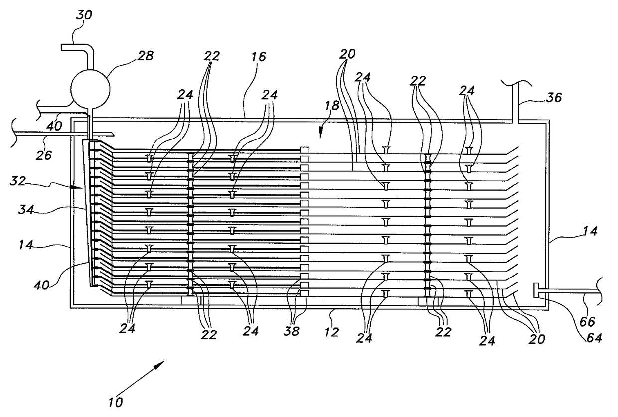
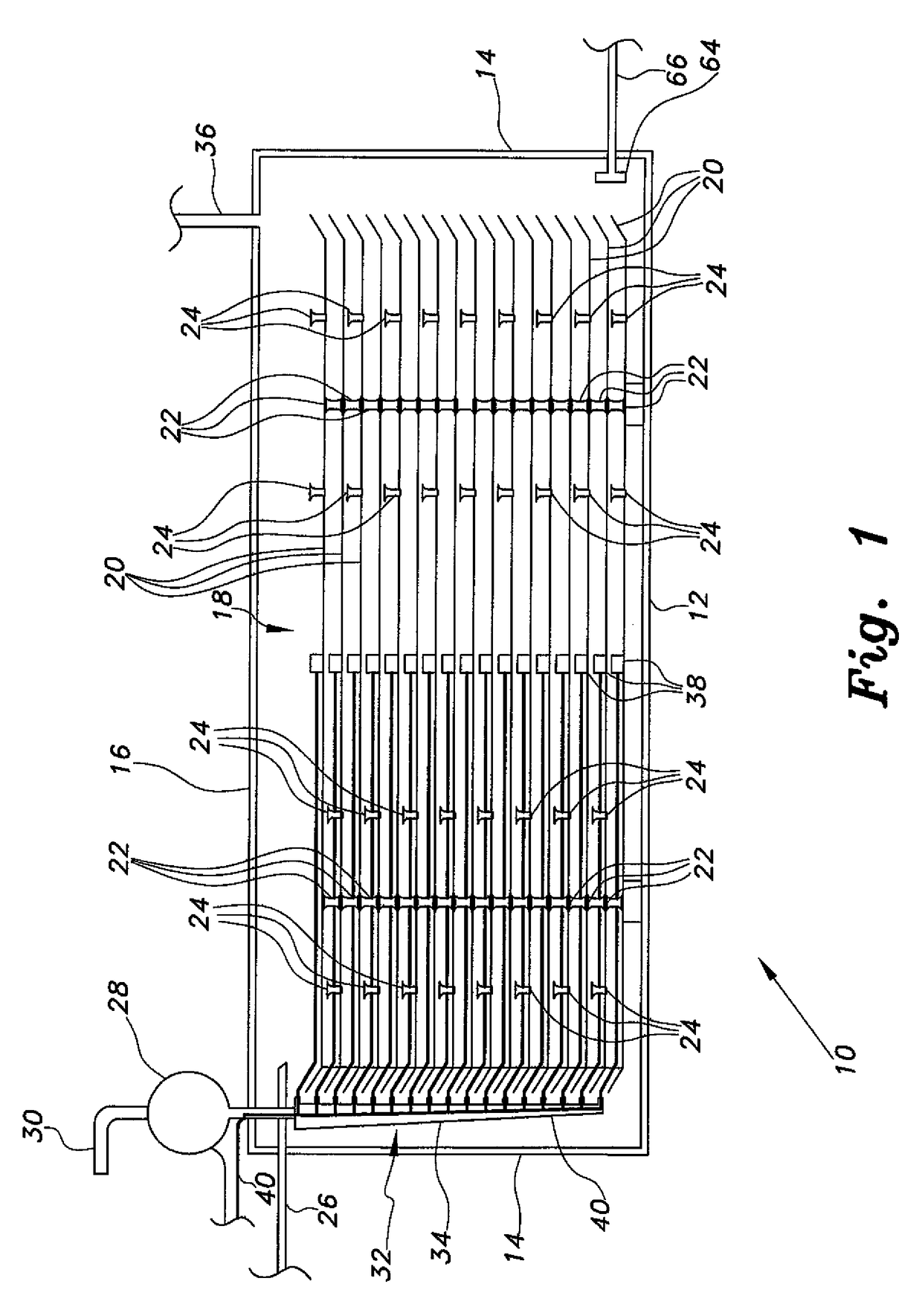
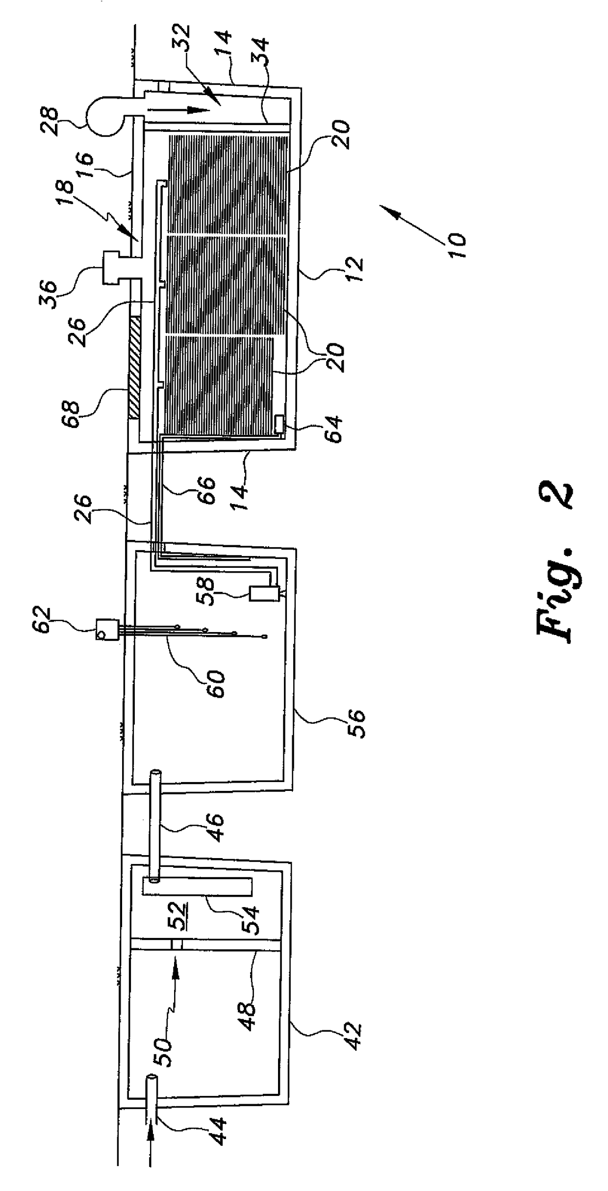
[0017]The interior of an exemplary evaporator tank 10 of the wastewater evaporator is illustrated as a side elevation view in FIG. 1. The evaporator tank 10 includes a floor 12, walls 14, and a top 16 defining an internal volume 18. The floor, walls, and top are preferably constructed of or lined with liquid impervious or waterproof materials in order to preclude leakage or seepage of effluent from the tank 10. A plurality of wide, shallow evaporator trays 20 are installed within the evaporator tank 10. Each of the evaporator trays 2...


PUM

PropertyMeasurementUnit
internal volumeaaaaaaaaaa
water surface areaaaaaaaaaaa
surface areaaaaaaaaaaa

Abstract

The wastewater evaporator provides for effluent evaporation in a septic system to eliminate need for a drain field. The evaporator tank contains a plurality of evaporator trays in a vertical array. Solids settle in the septic tank, and liquid effluent flows from the septic tank to the evaporator tank and cascades sequentially from the uppermost to the lowermost tray. The multiple trays increase the surface area of liquid contained therein, thereby greatly enhancing evaporation. An above-surface air pump and vent may be provided for air flow through the evaporator tank. An ultrasonic generator may be installed in each tray to increase the surface area of the effluent to enhance evaporation. An additional intermediate pump tank may be provided between the septic tank and the evaporator tank to control effluent flow and delivery to the evaporator tank. A sump pump in the pump tank periodically delivers effluent to the evaporator tank.

Description

CROSS-REFERENCE TO RELATED APPLICATION[0001]This application claims the benefit of U.S. Provisional Patent Application Ser. No. 61 / 671,438, filed Jul. 13, 2012.BACKGROUND OF THE INVENTION[0002]1. Field of the Invention[0003]The present invention relates generally to water treatment facilities, and particularly to a wastewater evaporator that evaporates wastewater effluent in a septic system to eliminate or minimize the need for an underground drain field.[0004]2. Description of the Related Art[0005]Homes and businesses in many suburban areas and nearly all rural areas are not connected to a sanitary sewer system, but rely upon individual septic tank and drain field systems. Such septic tank and drain field systems collect wastewater in the tank, and effluents drain out into the drain field where it is absorbed and dissipated into the surrounding soil.[0006]Such septic tank and drain field systems work reasonably well, are reasonably economical, and require little maintenance until r...

Claims


Application Information

Patent Timeline
Patent Type & Authority Patents(United States)
IPC IPC(8): C02F1/04B01D1/22C02F1/10B01D1/00B01D1/14B01D1/24C02F1/00B01D3/00
CPCC02F1/048B01D1/0088B01D1/14B01D1/22B01D1/24B01D3/006C02F1/004C02F1/04C02F1/10C02F2209/42
Inventor CLARK, GRETCHEN B.REYNOLDS, TIMOTHY C.
Owner CLARK GRETCHEN B
Learn More