
Toy top

a technology of rubber rotary shaft and toy top, which is applied in the field of toy top, can solve the problems of large and highly aggressive movement of the toy top on the game board, high frictional force generated by the top and the rubber rotary shaft, and low rotational continuity of the toy top. achieve the effect of reducing the resistance applied and high rotational continuity

Active Publication Date: 2017-03-21
TOMY CO LTD
View PDF16 Cites 19 Cited by
  • Summary
  • Abstract
  • Description
  • Claims
  • Application Information

AI Technical Summary

Benefits of technology

The present invention provides a toy top that can maintain high aggression and high rotational continuity in a battle game. The rubber of the toy top comes into contact with the game board, causing large and highly aggressive movement of the toy top in the first half of the battle game. In the last half of the battle game, the shaft tip segments constituting part of the outer periphery of the rotating shaft come into contact with the game board, maintaining the movement of the toy top. This ensures that the toy top can rotate smoothly and without stopping or starting again. The rubber of the toy top has a bottom end positioned above the bottom ends of the shaft tip segments, reducing resistance during the game. This allows the toy top to have high rotational continuity.

Problems solved by technology

Unfortunately, the toy top having the rubber rotary shaft that generates high frictional force during the rotation is inferior to a toy top having a plastic or metal rotary shaft in rotational continuity, although superior in aggression because of the large (rampageous) movement thereof.
In other words, the toy top having the rubber rotary shaft has high aggression but low rotational continuity.
In the first half of the battle game, the frictional segments of the toy top come into contact with the game board, causing large and highly aggressive movement of the toy top on the game board.
Unfortunately, this toy top exhibits low aggression in the last half of the battle game.

Method used


Image

  • Toy top
  • Toy top
  • Toy top

Examples


Embodiment Construction

[0036]Embodiments of a toy top according to the present invention will now be described with reference to the accompanying drawings.

>

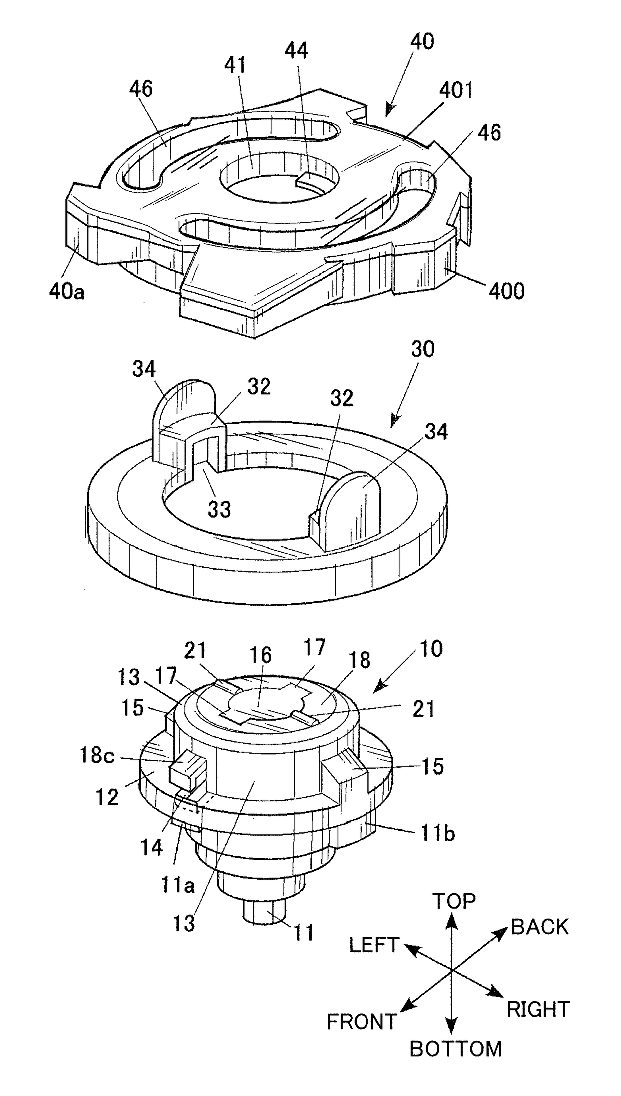
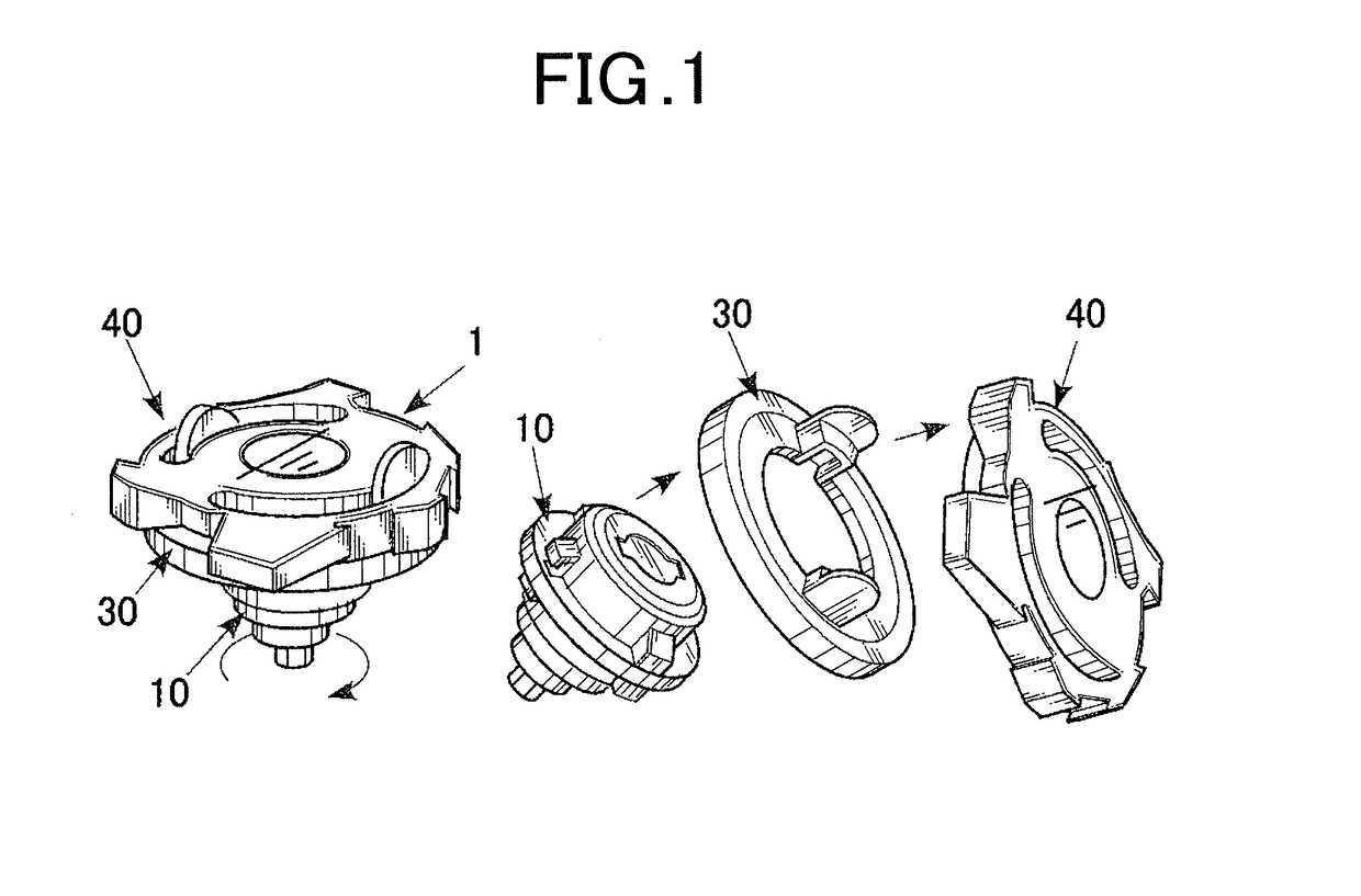
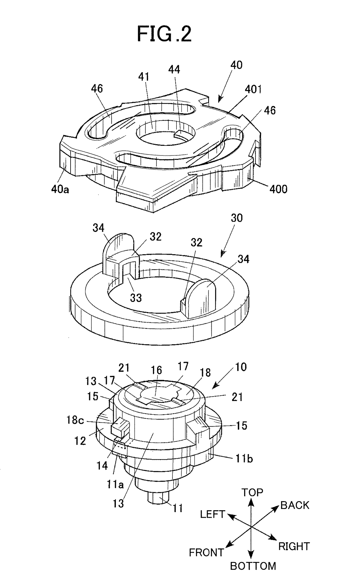
[0037]FIG. 1 illustrates the action of a toy top according to an embodiment of the present invention in the battle game. FIG. 2 is an exploded perspective view of the toy top according to the embodiment. FIG. 3 is an exploded cross-sectional perspective view of the toy top according to the embodiment. In this specification, the terms “top,”“bottom,”“left,”“right,”“front,” and “back” refer to the corresponding directions in FIGS. 2 and 3.

[0038]A toy top 1 according to the embodiment can be used in “spinning top battle games.” In detail, the toy top 1 can be used in a battle game in which the toy top of a winner collides with and dissembles a toy top 1 of an opponent, as illustrated on the right of FIG. 1, by the impact force.

[0039]With reference to FIGS. 2 and 3, the toy top 1 includes a shaft part 10, which constitutes a lower segment serving as a driv...


PUM


Abstract

A toy top includes a body and a shaft part. A rotating shaft of the shaft part includes plastic or metal shaft tip segments disposed at predetermined intervals in a circumferential direction of the rotating shaft. The shaft tip segment constitutes part of an outer periphery of the rotating shaft. The part of the outer periphery is configured to come into contact with the ground. Rubber is provided at the outer periphery of the rotating shaft so as to protrude outward beyond outer surfaces of the shaft tip segments. The rubber has higher frictional force than the shaft tip segments. The rubber is disposed between adjacent shaft tip segments in the circumferential direction.

Description

BACKGROUND OF THE INVENTION[0001]1. Field of the Invention[0002]The present invention relates to a toy top.[0003]2. Description of the Related Art[0004]Some known battle games involving toy tops determine winning and losing of the games by launching toy tops to each other such that the impact force knocks out the toy tops of the opponents or causes ejectable components on the bodies of the toy tops to pop off (for example, refer to JP H09-038337 A and JP 3109118 U).[0005]Although traditional toy tops have rotary shafts made of plastic or metal, recent toy tops for battle games have shafts of various elaborate designs. Examples of such a recent toy top include a toy top having a rotary shaft made of rubber.[0006]Unfortunately, the toy top having the rubber rotary shaft that generates high frictional force during the rotation is inferior to a toy top having a plastic or metal rotary shaft in rotational continuity, although superior in aggression because of the large (rampageous) movem...

Claims


Application Information

Patent Timeline
IPC IPC(8): A63H1/00A63H1/02
CPCA63H1/02
Inventor HORIKOSHI, KENJI
Owner TOMY CO LTD
Learn More