Cap with channels for forming a sealed cavity around fastener

a technology of nut caps and sealing cavities, applied in the direction of threaded fasteners, nuts, fastening means, etc., can solve the problem of unreasonably high installation force required to install the nut caps by hand, and achieve the effects of facilitating storage of the cap, facilitating the flow of sealant, and reducing stress concentration

Inactive Publication Date: 2017-03-21
AIRBUS OPERATIONS LTD
View PDF16 Cites 9 Cited by
  • Summary
  • Abstract
  • Description
  • Claims
  • Application Information

AI Technical Summary

Benefits of technology

[0009]The plurality of channels form a path along which the sealant may flow more freely as compared to the nominal gap provided between the side walls of the inner and outer cap members. This is due to the reduced effect of friction of the sealant with the walls, thanks to the reduced sealant to wall contact for a given cross-sectional area of sealant flow. The invention is therefore particularly advantageous when applied to caps for larger diameter fasteners, e.g. fasteners larger than approximately ¾″ diameter, which may otherwise not be suitable for hand installation, but enables a reduced installation force for all fastener diameters.
[0027]The cap members may be made of plastics material. The plastics material may be polyetherimide (PEI), for example. Plastic materials are generally cheap, light and easy to form whilst having the required resilience for the application.

Problems solved by technology

On larger installations, e.g. fasteners larger than approximately ¾″ diameter, an unreasonably high installation force is required to install the nut cap by hand.

Method used


Image

  • Cap with channels for forming a sealed cavity around fastener
  • Cap with channels for forming a sealed cavity around fastener
  • Cap with channels for forming a sealed cavity around fastener

Examples


Embodiment Construction

)

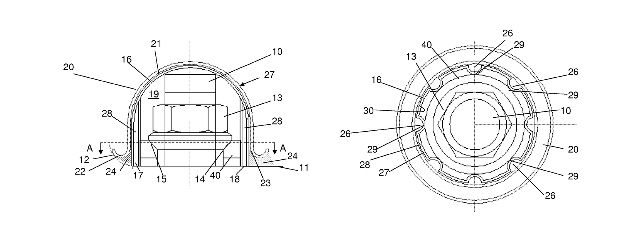
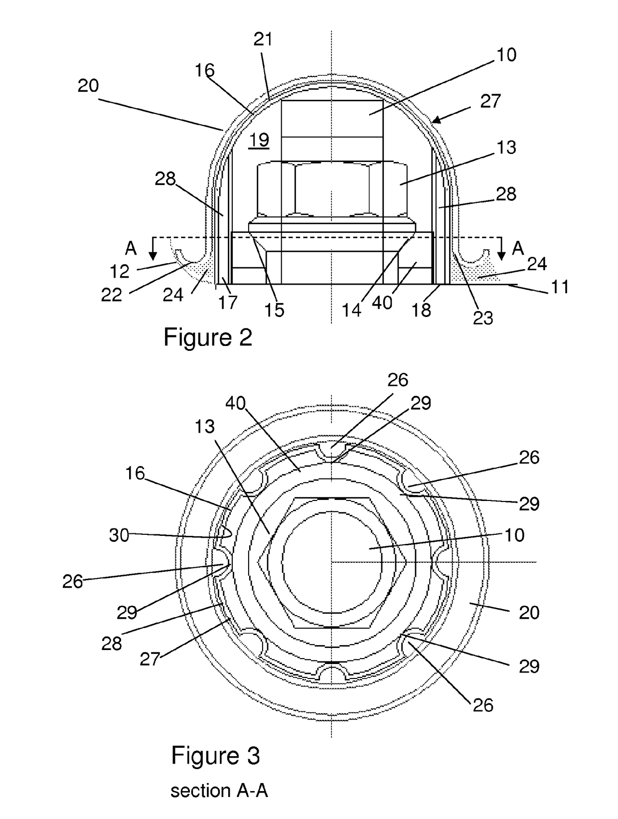
[0041]FIG. 2 is a side section view showing a metal bolt 10 passing through a composite panel 11. The panel has a raised feature 12 on one side, which may be for example fillets, ribs or spar caps. An internally threaded metal nut 13 is screwed onto the bolt 10 and has a convex spherical surface 14 which engages a concave spherical surface 15 of a washer 40. The spherical nut and washer enable the fastener to be securely fixed to the panel and permits angular misalignment if the bolt shank is not perpendicular to the panel.

[0042]A spark containment cap is fitted over the fastener. The cap has a two-part construction with an outer cap 20 fit onto an inner cap 16 so that the inner cap 16 is nested within the outer cap 20. The caps 16, 20 have a domed shaped as indicated at 27 which reduces exposure to damage (for instance by being kicked by the foot of an installer) and minimises stress concentration. The caps 16, 20 are formed from a polymer such as polyetherimide ULTEM 2400. The in...


PUM


Abstract

A cap for forming a sealed cavity around one end of a fastener, the cap having a two-piece construction comprising an outer cap member and an inner cap member. A quantity of sealant is provided between the inner and outer cap members which, upon installation of the cap, is urged to flow between the inner and outer cap members and collect at the base of the outer cap member, to form a bead of sealant around the circumference of the cap, sufficient to adhere the cap to the structure when the sealant cures. A plurality of channels are provided between the inner and outer cap members to facilitate the flow of sealant.

Description

RELATED APPLICATIONS[0001]The present application is a National Phase of International Application Number PCT / GB2013 / 052868, filed Nov. 1, 2013, and claims priority from Great Britain Application Number 1220002.8, filed Nov. 6, 2012.FIELD OF THE INVENTION[0002]The present invention relates to a cap for forming a sealed cavity around one end of a fastener and a method of installing such a cap.BACKGROUND OF THE INVENTION[0003]FIG. 1 is a side view of part of a fastener assembly passing through a composite panel 1. The assembly comprises an externally threaded bolt 2, an internally threaded nut 3, and a washer 4. In the event of a lightning strike hitting the composite panel 1 and attaching to the fastener, sparking, plasma or out-gassing may occur at the locations 5 shown in FIG. 1.[0004]A known method of providing spark suppression is described in WO 2012 / 107741. A volume of gas is enclosed by a cap around the fastener. The gas provides spark suppression for arcing that may occur bet...

Claims


Application Information

Patent Timeline
Patent Type & Authority Patents(United States)
IPC IPC(8): F16B37/14B64D45/02
CPCF16B37/14B64D45/02
Inventor DOBBIN, RICHARD
Owner AIRBUS OPERATIONS LTD
Why Eureka
Try Eureka