Collisionless flying of unmanned aerial vehicles that maximizes coverage of predetermined region

Active Publication Date: 2017-03-21
UNITED STATES OF AMERICA THE AS REPRESENTED BY THE SEC OF THE ARMY
View PDF26 Cites 27 Cited by
  • Summary
  • Abstract
  • Description
  • Claims
  • Application Information

AI Technical Summary

Benefits of technology

[0009]The present invention relates to a system and method for ensuring collisionless flight of three or more unmanned aerial vehicles (UAVs). Collisionless flight is achieved by overlaying a circulant digraph with certain characteristics over a model of the area to be flown. Each UAV then executes a flight path corresponding to a directed cycle of the circulant digraph where each vertex of the circulant digraph corresponds to two waypoints. The circulant digraph includes more vertices than the number of unmanned aerial vehicles and the number of vertices is divisible by the number of UAVs. Additionally, the circulant digraph has a first jump of 1, a second jump of one less than then number of UAVs. To maximize coverage, each of the vertices of the circulant digraph may then be individually updated such that they satisfy two tests: a convexity test and an isosceles avoidance test. The updated flight path of each UAV may then be relayed from a control station to each UAV.
[0010]According to a first aspect of the invention, a method for ensuring collisionless flight of three or more unmanned aerial vehicles over an area comprises the steps of: constructing a circulant digraph representing a portion of

Problems solved by technology

UAV collisions can result in financial loss, mission failure and possibly even injury or loss of life.
This additional hardware increases the size and cost of the UAV.
Additionally, location sensing and intricate flight coordination becomes increasingly complex as the number

Method used


Image

  • Collisionless flying of unmanned aerial vehicles that maximizes coverage of predetermined region
  • Collisionless flying of unmanned aerial vehicles that maximizes coverage of predetermined region
  • Collisionless flying of unmanned aerial vehicles that maximizes coverage of predetermined region

Examples


Embodiment Construction

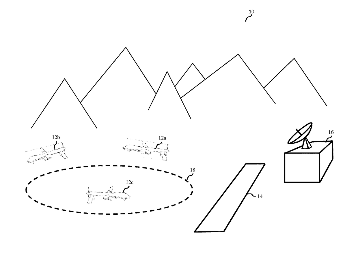
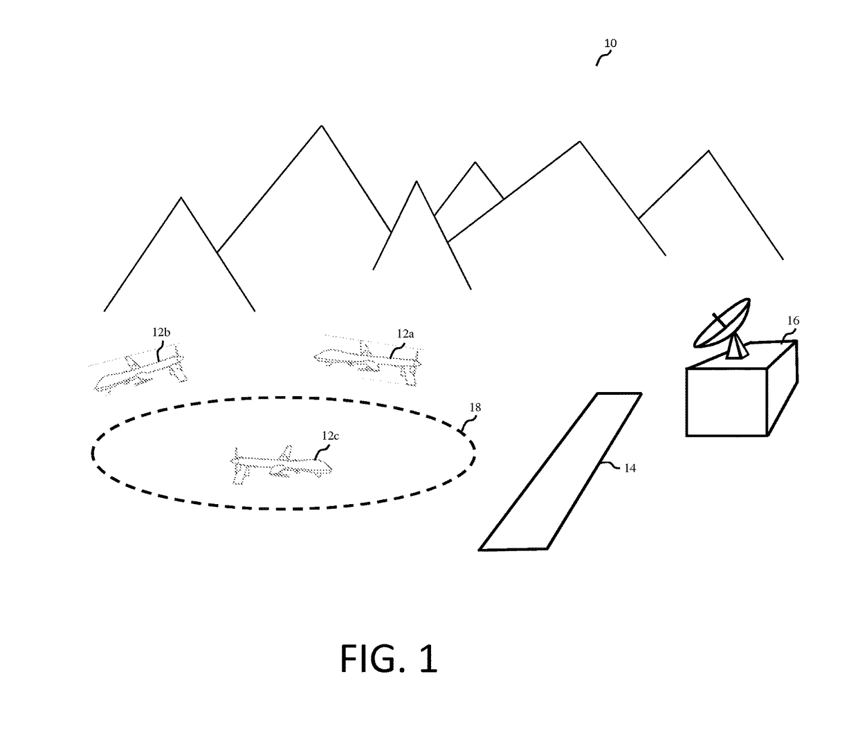
[0029]The present invention relates to a system and method for ensuring collisionless flight of three or more unmanned aerial vehicles (UAVs). Collisionless flight is achieved by overlaying a circulant digraph with certain characteristics over the area to be flown. Each UAV is then assigned to a flight path corresponding to a directed cycle of the circulant digraph where each vertex of the circulant digraph corresponds to two waypoints. To maximize coverage, each of the vertices of the circulant digraph may then be updated such that they satisfy two tests: a convexity test and an isosceles avoidance test. The updated waypoint may then be relayed from a control station to each UAV.

[0030]Advantageously, each UAV does not require any collision avoidance sensors or knowledge of the position of other UAVs in the area. This reduces the cost, size and complexity of the UAVs. Further, each UAV does not require communication with the other UAVs. Accordingly, the UAVs may be a heterogeneous m...


PUM


Abstract

Collisionless flight is achieved by overlaying a circulant digraph with certain characteristics over a model of the area to be flown. Each UAV then executes a flight path corresponding to a directed cycle of the circulant digraph where each vertex of the circulant digraph corresponds to two waypoints. The circulant digraph includes more vertices than the number of unmanned aerial vehicles and the number of vertices is divisible by the number of UAVs. Additionally, the circulant digraph has a first jump of 1, a second jump of one less than then number of UAVs. To maximize coverage, each of the vertices of the circulant digraph may then be individually updated such that they satisfy two tests: a convexity test and an isosceles avoidance test. The updated flight path of each UAV may then be relayed from a control station to each UAV.

Description

FEDERAL RESEARCH STATEMENT[0001]The invention described herein may be manufactured, used, and licensed by or for the U.S. Government for U.S. Government purposes.BACKGROUND OF INVENTION[0002]Field of the Invention[0003]The present invention relates to autonomous vehicles, and more particularly to flight paths of autonomous vehicles.[0004]Related Art[0005]Unmanned Aerial Vehicles (UAVs), also known as drones, are critical in the collaborative engagement, surveillance and monitoring of enemy territory in today's military conflicts and operations. Increasingly, UAVs are also being used in commercial and civilian applications, as well. UAVs are used by law enforcement agencies to monitor and surveille an area, by farmers to monitor crops for pests or water requirements, by scientists to conduct research or by activists to prevent wildlife poaching or other misuse of natural resources.[0006]Additionally, as UAVs become less expensive their use becomes more economical. Where once a single...

Claims


Application Information

Patent Timeline
IPC IPC(8): G01C23/00B64D47/08G08G5/00G08G5/04G05D1/00G05D3/00G06F7/00B64C39/02G05D1/10G06F17/00
CPCG05D1/104B64C39/024B64D47/08G08G5/0034G08G5/0043G08G5/045G08G5/0069G08G5/0082B64U10/25B64U2101/30B64U2201/102
Inventor BOGDANOWICZ, ZBIGNIEWPATEL, KETULA
Owner UNITED STATES OF AMERICA THE AS REPRESENTED BY THE SEC OF THE ARMY
Why Eureka
Try Eureka