Antenna structure

a technology of antenna structure and antenna structure, applied in the direction of resonant antenna, elongated active element feed, radiating element structure, etc., to achieve the effect of reducing the sar (specific absorption rate) of the antenna structure operating

Active Publication Date: 2017-03-21
ACER INC
View PDF12 Cites 0 Cited by
  • Summary
  • Abstract
  • Description
  • Claims
  • Application Information

AI Technical Summary

Benefits of technology

[0012]In some embodiments, a current maximum point of the high-frequency band is positioned at the second radiation branch, so as to reduce an SAR (Specific Absorption Rate) of the antenna structure operating in the high-frequency band.

Problems solved by technology

It becomes a critical challenge for current designers to design an antenna element which has good communication quality and meets the requirements of the law.

Method used


Image

  • Antenna structure
  • Antenna structure
  • Antenna structure

Examples


Embodiment Construction

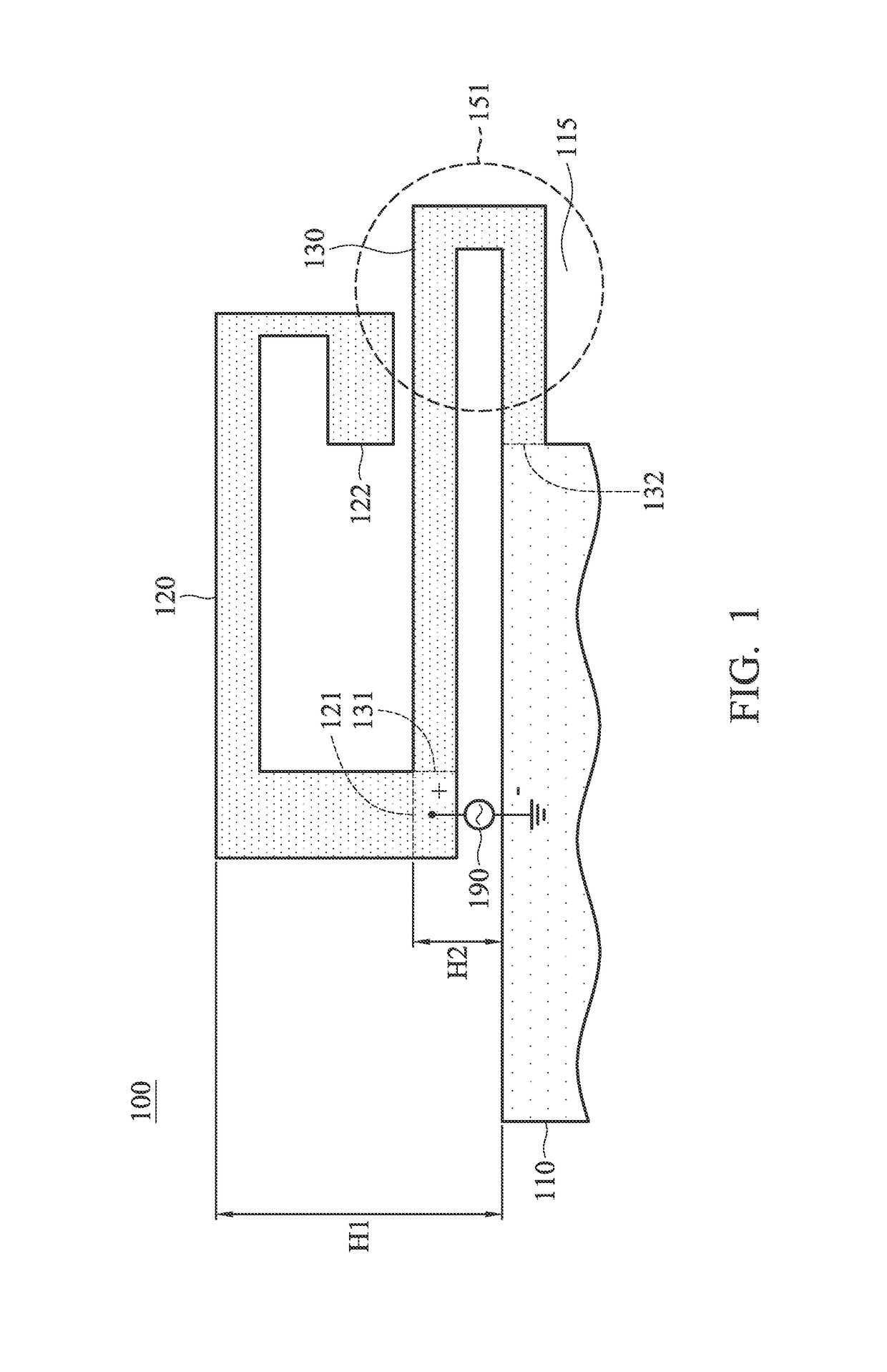
[0021]In order to illustrate the foregoing and other purposes, features and advantages of the invention, the embodiments and figures of the invention will be described in detail as follows.

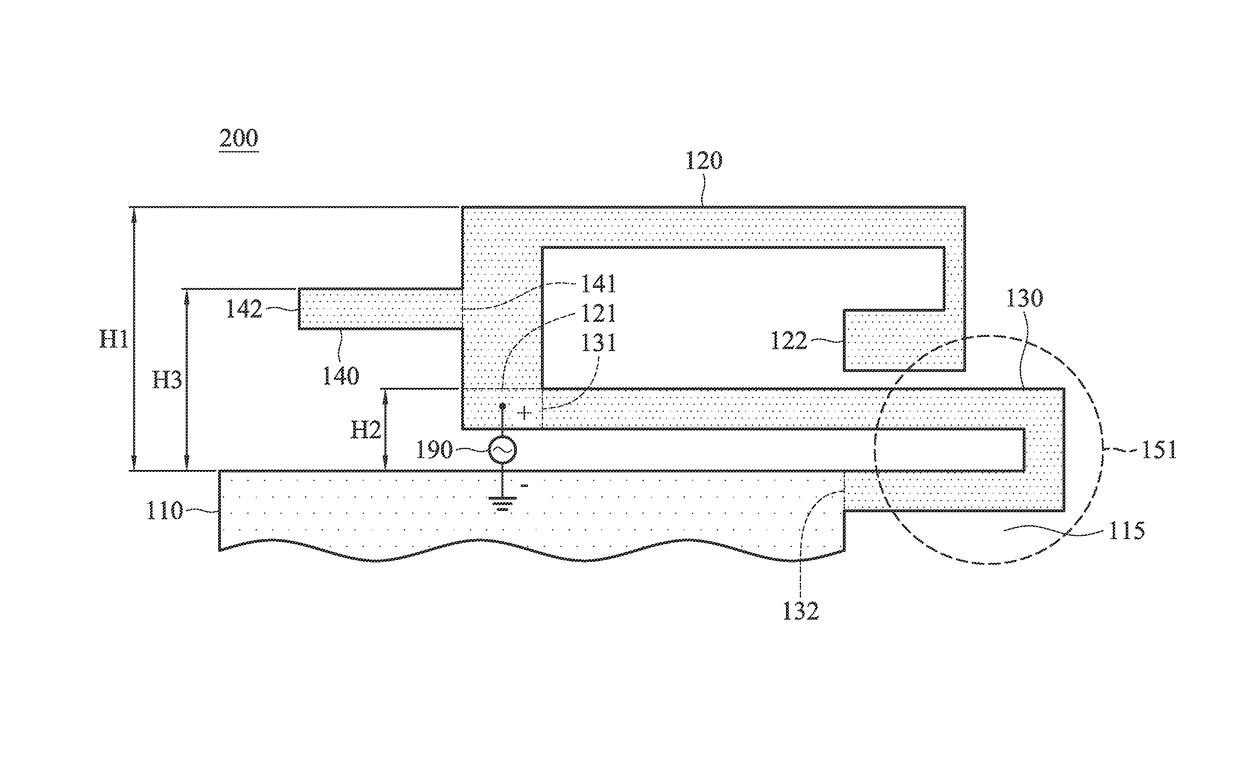
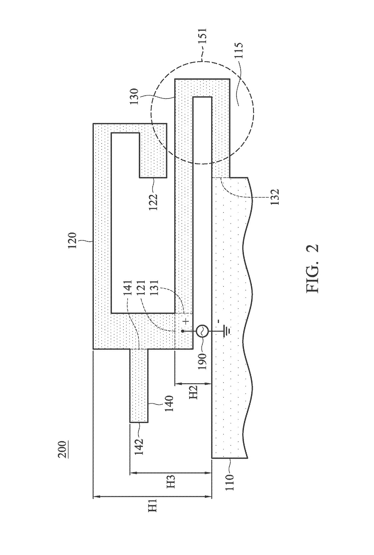
[0022]FIG. 1 is a diagram of an antenna structure 100 according to an embodiment of the invention. The antenna structure 100 may be applied in a mobile device, such as a smartphone, a tablet computer, or a notebook computer. As shown in FIG. 1, the antenna structure 100 at least includes a ground element 110, a first radiation branch 120, and a second radiation branch 130. The antenna structure 100 may be disposed on a dielectric substrate, such as a system circuit board or an FR4 (Flame Retardant 4) substrate. The ground element 110, the first radiation branch 120, and the second radiation branch 130 may be made of metal materials, such as copper, silver, aluminum, iron, or their alloys. The total length of the second radiation branch 130 is substantially equal to the total length of the first ra...


PUM


Abstract

An antenna structure includes a ground element, a first radiation branch, and a second radiation branch. The first radiation branch has a first end and a second end. The first end of the first radiation branch is coupled to a signal source. The second end of the first radiation branch is open. The second radiation branch has a first end and a second end. The first end of the second radiation branch is coupled to the signal source. The second end of the second radiation branch is coupled to the ground element. The length of the second radiation branch is substantially equal to that of the first radiation branch.

Description

CROSS REFERENCE TO RELATED APPLICATIONS[0001]This application claims priority of Taiwan Patent Application No. 104112169 filed on Apr. 16, 2015, the entirety of which is incorporated by reference herein.BACKGROUND OF THE INVENTION[0002]Field of the Invention[0003]The disclosure generally relates to an antenna structure, and more particularly, to an antenna structure for reducing an SAR (Specific Absorption Rate).[0004]Description of the Related Art[0005]With advancements in mobile communication technology, mobile devices such as portable computers, mobile phones, multimedia players, and other hybrid functional portable electronic devices have become more common. To satisfy user demand, mobile devices can usually perform wireless communication functions. Some devices cover a large wireless communication area; these include mobile phones using 2G, 3G, and LTE (Long Term Evolution) systems and using frequency bands of 700 MHz, 850 MHz, 900 MHz, 1800 MHz, 1900 MHz, 2100 MHz, 2300 MHz, a...

Claims


Application Information

Patent Timeline
Patent Type & Authority Patents(United States)
IPC IPC(8): H01Q1/38H01Q1/24H01Q5/371H01Q7/00H01Q9/04H01Q5/00H01Q9/42
CPCH01Q5/371H01Q1/243H01Q7/00H01Q9/42
Inventor CHANG, KUN-SHENGLIN, CHING-CHIYANG, CHUNG-WENWANG, CHUAN-CHUNCHUNG, KUAN-JEN
Owner ACER INC
Why Eureka
Try Eureka